Materials Archives - GF Machine Shop LTD.

December 25, 2024
Laser-Cut-Aluminum-1280x640.jpg

Laser-cutting technology is gradually receiving wide acceptance across different sectors because of the precision, flexibility, and speed offered. Among the metals machining, CO2 lasers slicing aluminum materials are often inquired. In this article, we’ll try to establish how different CO2 lasers perform when cutting this resilient metal and if the laser type is suitable for aluminum in the first place.

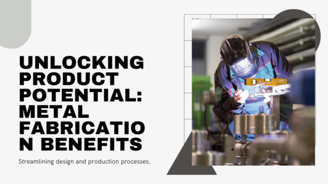
A brief on the characteristics and usage of CO2 laser and aluminum

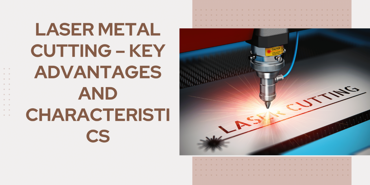
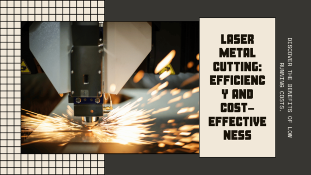
Carbon dioxide lasers are cutting technology that is referred to as CO2 lasers in short form. Its nearly infrared lasers emit light using a CO2 gas mixture of nitrogen, hydrogen and CO2. This light is very intense and is employed in the process of heating or oxidizing a solid (material), for example, metal, wood or plastic.

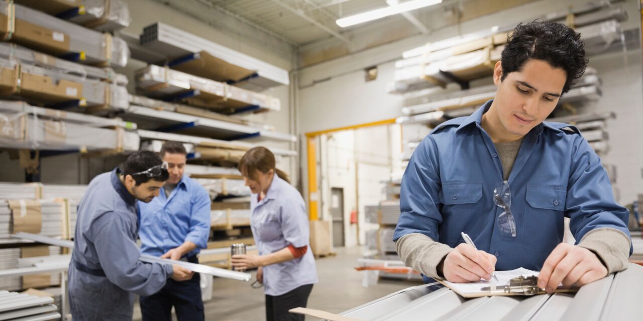
Aluminum is a versatile metal used in structural drills; it has desirable physical/ mechanical and corrosion characteristics and is extensively utilized in aerospace, automobile and constructional applications. That is, the thermal and electrical conductivity of the metal can influence the laser-cutting process.

Characteristics of Aluminum and Its Adaptability to Laser Cutting

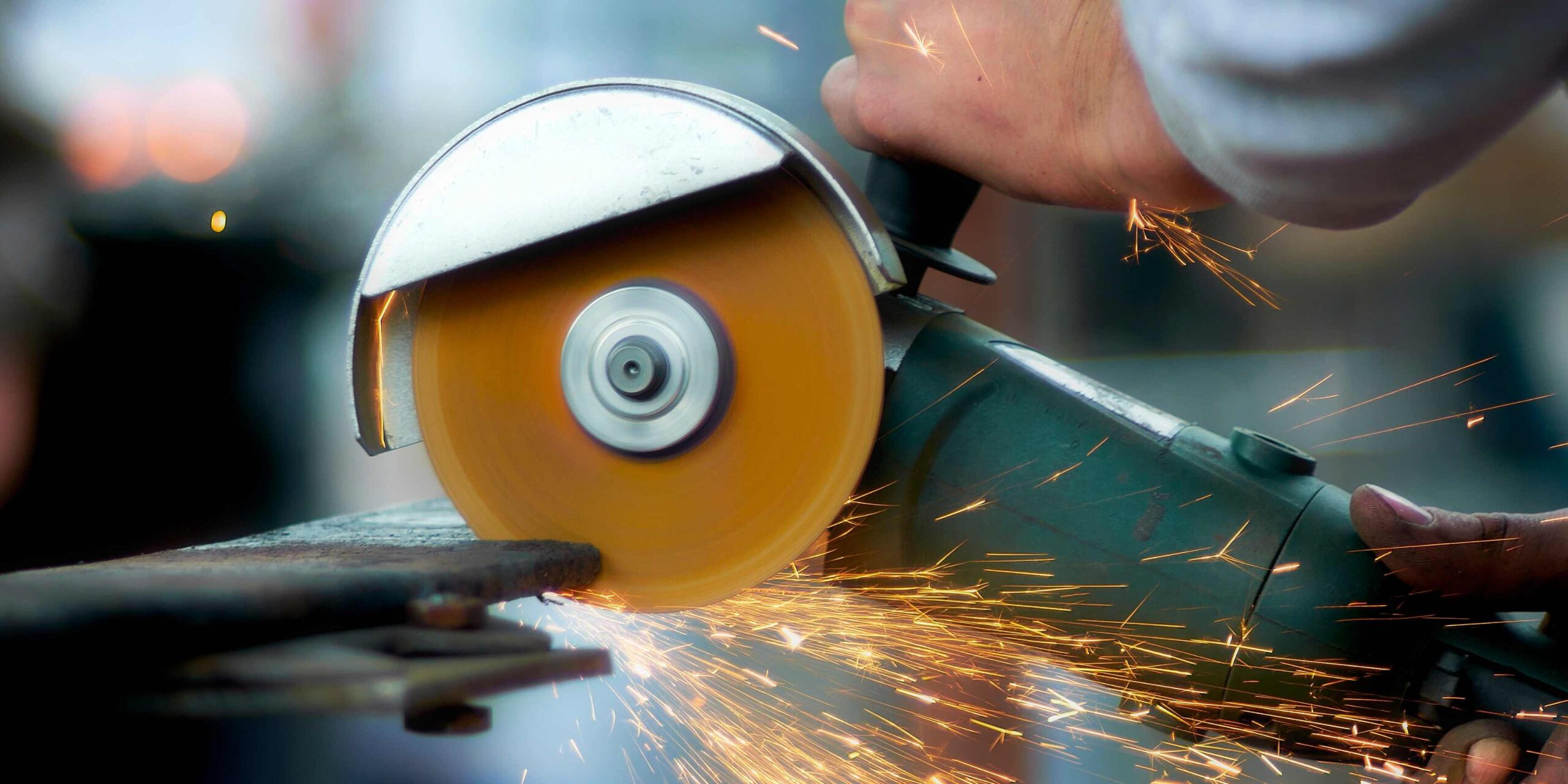
Because of the properties of aluminum, this material is somewhat difficult to apply with laser technology to cutting. It gives high reflectivity that a major part of the laser beam can be reflected off the surface without being absorbed. By reducing efficiency and more usage of energy, the cutting tools will wear out sooner and take more time to cut.

Secondly, aluminum creates a cover layer of oxidation on its surface and thus can act as a shield against rusting but also presents a challenge to the laser cutting process. This oxide layer needs to be passed through to allow the laser to cut through the metal and get an effective result.
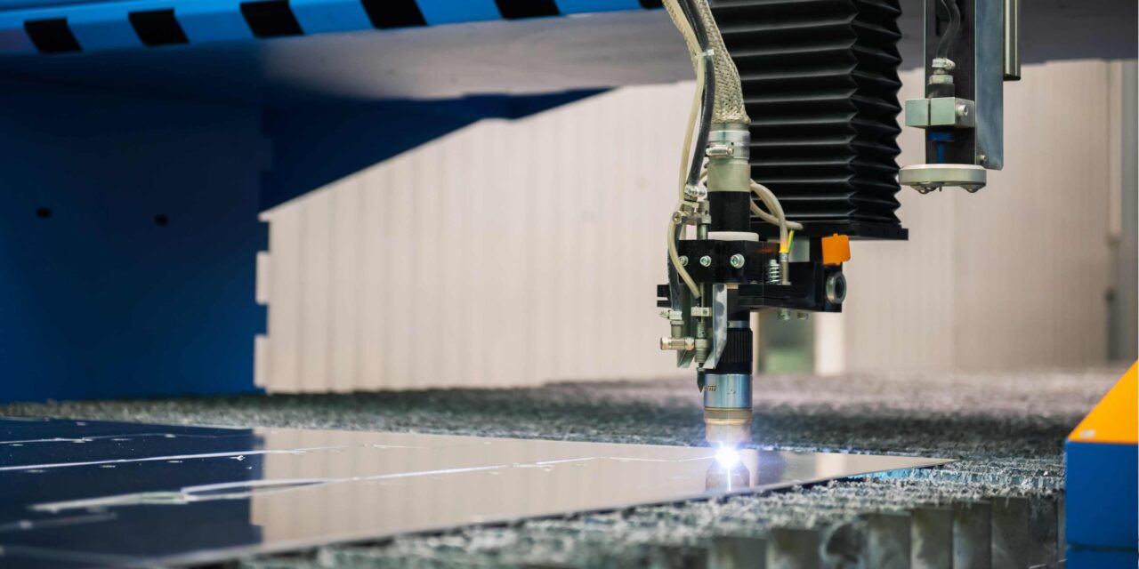
How CO2 Lasers Work

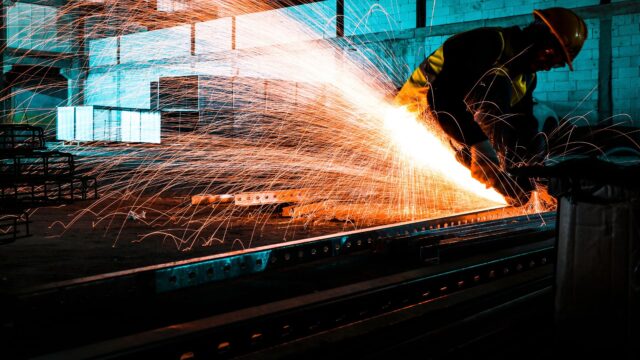
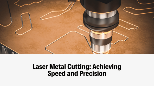
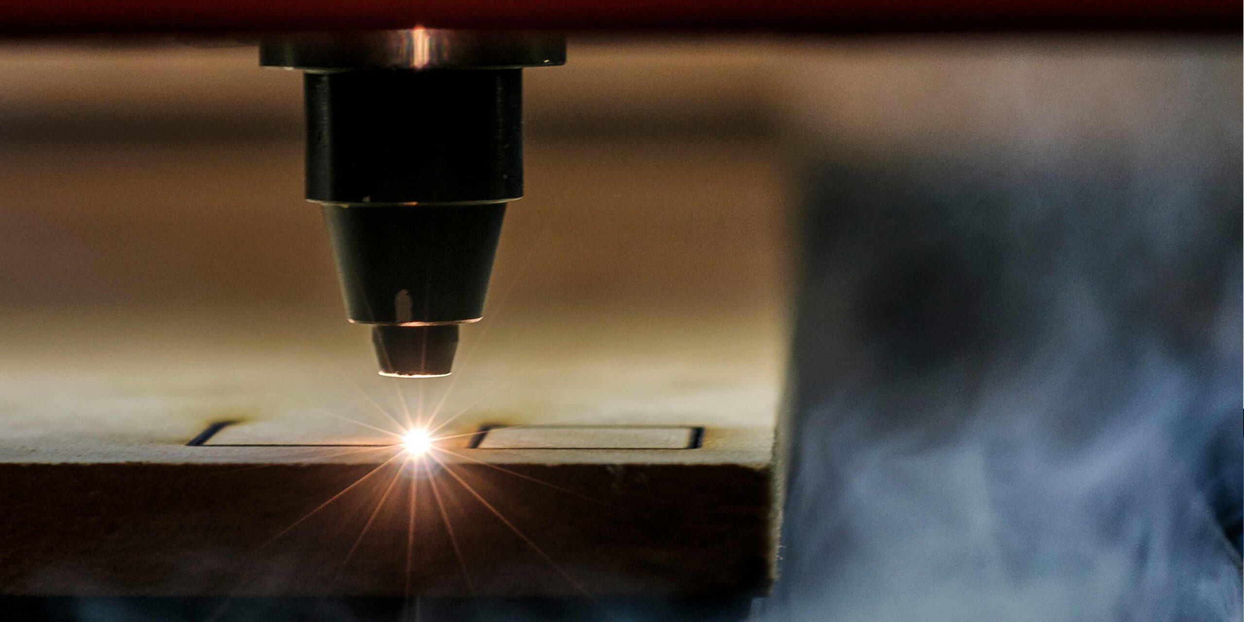
CO2 lasers operate by passing current through gases inside a laser chamber. The excited gas releases its energy in the form of a laser beam, and this can be aimed and converged to bring about the required cutting topology. The energy from the beam is transferred to the stuff, in this case, heating the material and vibrating it enough to melt, evaporate or burn to make the cut desired.

Laser Cutting Aluminum: Advantages and Disadvantages

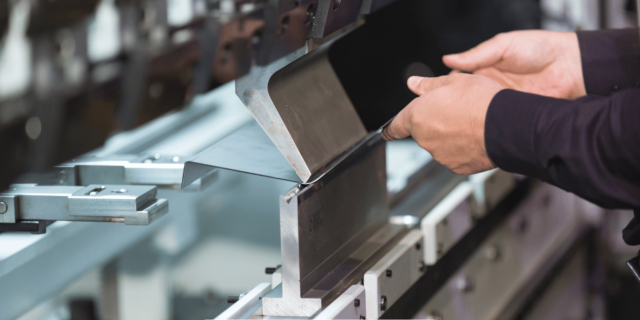
Using laser cutting in aluminum offers a number of advantages over conventional cutting techniques due to enhanced accuracy, a slim margin of heat-influenced area, and enhanced rates of cutting. These advantages may lead to the generation of improved quality parts and decreased manufacturing expenses. One limitation of laser cutting is that if aluminum, then it has limitations in reflective material as well as the coating chances with oxide layers.

Technical Issues Involving the Utilization of CO2 Laser for Cutting Aluminum

Cutting Aluminum

For a CO2 laser working the right technological parameters have to be there to enable proper cutting of the material.

These factors include:

– Laser power: It is possible to increase the density of the laser in order to avoid the influence of the aluminum’s high reflectivity and the presence of a thin oxide layer on its surface. This helps put the laser through the material in question, hence providing a cleaner cut through the item.

– Cutting speed: Using a low cutting speed will enable the laser beam to take sufficient time to permeate the material besides breaking through the oxide layer. It could cause a cleaner and a smoother incision.

– Assisting gases: Thus, to optimize the cutting process, an assisting gas can be applied to facilitate the removal of molten metal from the cutting area. The typical helping gases of laser-cutting aluminum are oxygen, nitrogen and air.

– Focus: During cutting aluminum it is very important to set the laser beam correctly. When the beam is well-focused, then expect a neat and accurate cut.

A comparison of CO2 Lasers with other laser types

But there are other types of lasers used in cutting aluminum, such as fibre laser and UV laser. In that case, these lasers may have advantages over CO2 lasers with respect to speed of cutting and utilization. But CO2 lasers also still count as popular because costs are relatively lower than most and can cut through most material types.

The typical uses of CO2 laser cutting of aluminum

CO2 laser cutting of aluminum is used in a wide range of industries and applications, including:

– Aerospace: Laser cutting is applied in the fabrication of accurate components of aircraft and spaceships.

– Automotive: Cars employ aluminum in the body and other parts, and cutting normally involves the use of CO2 lasers.

– HVAC: Today most of duct work, vents and other HVAC products are fabricated from aluminum using the laser cutting technique.

– Medical: Medical devices and equipment made of aluminum components are cut with the use of CO2 lasers.

– Architectural: Other applications of laser cutting include making clips and panels, metal cladding, and certain architectural embellishments.


December 5, 2024
1-1-1280x640.jpg

Using fabrics in different projects that can be attached to metal surfaces brings a lot of potentialities in the function of upholstery, fashion designing, and home interior decoration, among others, such as mixed media art. The procedure can also be a bit delicate since glass and carbon fibres do not share many characteristics, such as flexibility, mass or electrical conductivity. Here, you will find an overview of different techniques that are used in attaching fabric to metal, the advantages and disadvantages of each, and step-by-step instructions on how to sew them.

Materials Needed

To effectively attach fabric to metal, you’ll need the following materials:

1. Any fabric, which could be natural fabric, synthetic fabric or blended fabric.
2. Sheet metal or metallic piece (copper, brass, iron steel or any other preferably a conducting material).
3. Adhesive or fasteners
4. Sandpaper with medium abrasive grit (220 and higher).
5. Ruler
6. Pencil or fabric marker
7. Cutting tools either scissors or a utilitarian knife.
8. Cutting mat
9. Work gloves (for safety)
10. Clamps (if needed)

Preparing the Metal Surface

However, some preparations should still be made before attaching the fabric to the metal. This includes stripping by brushing off any burr, rust, paint or any material that will hinder the fabric from sticking to the metal.

Cleaning the Metal

First of all, moist the surface with water to ensure that the metal is free from dust and other dirt particles. If that is present, you can scrub it off with a wire brush or steel wool.

Sanding the Metal

To enhance that critical connection, you will be forced to slightly roughen the surface of the metal. It is then recommended that to use sandpaper of 220 grit or higher to sand the metal – covering the whole area of the substrate where you intend to join the fabric too. It can be done using a handheld sanding block, or sanding disk of an electric sander, or just sandpaper pasted to a wooden block. Make sure you have safety glasses and work gloves to protect you from objects that may fly around during handling.

Fabrics are cut according to the size required

Fabrics are cut according to the size required

When the metal surface is ready, the fabric needs to be measured and cut to fit the metal’s surface. For a proper fitting, you can stencil the measurement of the metal onto the fabric of use, cutting a piece of fabric slightly bigger than the metal dimensions.

Marking the Fabric

Measure the area on the fabric that you want to attach to the metal with a ruler and pencil or fabric marker. You should then opt to add the seam allowance around the edges to provide tight margins.

Cutting the Fabric

If your fabric has been drawn with lines, cut them using a pair of scissors or a utility knife.

Attaching Fabric to Metal

We’ll explore three popular methods: adhesive, staple and rivets.

Adhesive Method

Copper and brass worked well when the method was employed with thin blankets of fabrics such as perlite cotton and other lightweight synthetic textiles.

Choosing the Right Adhesive

Choose an adhesive for connecting two dissimilar materials such that one is metal and the other is fabric. Using E6000 craft adhesive or if it has to be a fabric as well as leather adhesive with a little more thickness might be ideal.

Applying the Adhesive

Spread a thin, even layer of sticky glue over the sandwich part of the metals that were sanded and to where the fabric must be fitted. For these adhesives, one can use a brush, or an applicator gun also depending on the adhesive in the process.

Attaching the Fabric

Put the fabric over the metal and arrange the edges as necessary. That is, fold it tightly on the surface of the metal with force from the middle to the edge. Eliminate any air bubbles by running a flat implementation tool, such as a butter knife or any straight edge over the polymer layer.

Staple Method

Suitable for rigid and soft metal and heavy fabrics such as denim or canvas material, this works perfectly.

Choosing the Right Stapler

Choose a stapler that will handle the thicker range denoted by the point range and that is made for such use. An upholstery stapler or a fabric stapler will apply the most effectively for this.

Attaching the Fabric

Start by laying the fabric right on top of the metal, and then ensure you have the edges correctly aligned. Pull the fabric tight with one hand and, using the other, drop a staple through the fabric and the metal in order to fix it. Carry on working on the edges, staple occasionally, approximately one inch at a time, or wherever necessary to keep the fabric on the board.

Rivet Method

Rivets provide a strong permanent fastener similar to metal and heavyweight fabrics. This method can be used for cosmetic or utilitarian reasons, such as that of a patch or piece of apparel no longer functional.

Choosing the Right Rivets

When selecting the rivets, one should ensure that they are slightly smaller than the thickness of the fabric. Copper, brass or steel rivets are chosen for use commonly;

Preparing the Rivets

For the final step, crimp or pin the rivet, depending on the type and size of the rivet. You will get only the cup and a seam of the tail at the bottom, which will be situated beneath the material.

Attaching the Fabric

Position the fabric over the central part of the rivet cup and make sure that the fabric is parallel to the metal surface. It is then flattened over the metal surface using the rivet setter or the hammer to make a crimp head of the rivet. Carry on this process right along the edges until the fabric is joined to the backboard well.

Finishing Touches

After that, an additional ornament such as fringe, lace or beads will give a finished look to this particular piece of metal.


November 5, 2024
How-to-calculate-the-shear-force-and-bending-moment-1280x640.jpg

One of the most critical areas of investigation in structural engineering is the behavior of beams under load. These behavior characterizations are commonly defined by the shear force and the bending moment. Shear force and bending moment diagrams are beneficial and popular aids that engineers use to explain, design, and anticipate the behaviour of beams under different loads. In this article, let us discuss the procedures for determining the shear force and bending moment together with the methods for producing the respective diagrams.

Shear Force Calculation

Shear force (V) is the force acting on a beam segment’s point perpendicular to that segment’s longitudinal plane. They occur from the unsymmetrical sharing of external load and reactions that act on a specific part of the structure. When determining shear force, it is possible to use three approaches: the direct, Graphical, and Numerical. In this case, we only discuss the direct method, which is much simpler and relevant for most applications.

Definition of Sign Convention

When determining the shear force, there must be a convention of its sign, which must be positive or negative.

The most common convention is as follows:

-It should also be mentioned that a positive sign is assigned to any vertical forces acting downwards.

-It should be noted that the vertical forces are hostile specifically.

-Left shear forces are positive, and right shear forces are hostile.

Step-by-step Calculation

1. Determine all point loads, distributed loads, and reactions located at the beam.

2. Generally, we select an origin (slightly to the left of the beam) and assign the intrinsic + ve and – ve signs to the former.

3. Subdivide the beam into a small elemental length (Δx, which is a differential length).

4. Find out the resultant force applied on each part of it (with point loads as well as the distributed loads and the reactions).

5. Force that stays at a specific point of the beam is the sum of shear forces accumulated in the narrowed segment of the beam located on the left side of this point only.

Example: A simply supported beam having a point load (P) at mid-span and a uniformly distributed load (w) covering the whole span of the beam of length (L).

1. Point loads: P (at the center of the beam)

2. Distributed load: w (which is evenly distributed throughout the span of the beam).

3. Reactions: R1 and R2 (at the supports)

4. Calculate the reactions: R1 = R2 = wL/2

5. Break down the beam. The shear force at any point to the left of the center is given by the expression:

for ( x < L / 2 ) ;
x : V ( x ) = w ( 0 ) – w ( L ) x + w L / 2.
V(x) = w(x) – P + wL/2 for L/2 < x ≤ L

Bending Moment Calculation

Force, what was felt at a beam segment, due to load transfer along the length of the beam is called bending moment (M). It is the outcome of an external loads reaction and shear forces which come into play in any fixed segment of structure. It is also possible to calculate the bending moment through a direct method, which deserves our attention below.

Definition of Sign Convention

Similar to shear force, a sign convention is necessary for the calculation of the bending moment:

-Clockwise moments are good ones.

-Moments that are counterclockwise are negative.

-Moments of the applied loads occurring at the left of the point are taken as positive, and at the right of the end, are taken as unfavorable.

Step-by-step Calculation

1. All the point loads, distributed loads, and reactions that are on a beam should be determined.

2. Pick a reference axis (typically the left end of the beam), and then assign plus (+) and minus (-) signs.

3. Subdivide the beam into small segments of equal dimensions required to be considered (Δx).

4. Point load, distributed load, reaction, or shear force stretches are determined, then, the force or net moment through segments of a beam for point loads, distributed loads, reactions, or shear forces.

5. The algebraic sum of moments of the forces applied to the beam up to a given point that is acting on the beam segment.

Using the same example as before, the bending moment at any point x to the left of the center is given by the expression:

M(x) = w(x^2)/2 – wLx/2 For 0 ≤ x ≤ L/2

Shear force and Bending moment diagrams

These are to be sized after getting the shear force and/or bending moment values of a segment, and the respective diagrams may be plotted. They show how shear force and bending moment change across the beam (and give a graphical description of how a beam behaves under load).

The steps for plotting these diagrams are as follows:

Shear Force Diagram

1. Shear force values are graphed and mapped to the respective points on the beam.

2. Connect the points together in perfectly lit, straight, and beautiful elegant lines.

3. If necessary, find the slope of the distributed loads that will be useful in extending the lines between the data points.

Bending Moment Diagram

1. Plotting the variation of bending moment as a function of a specific coordination point on the beam.

2. Make a straight line between the points.

3. If necessary, use the slope of the distributed loads and the shear force diagram in order to guide you in drawing lines between the data points.

4. Find points of inflection which marks the change of direction of bending moment from tension to compression or vice versa.

Through these diagrams, engineers are well positioned in identifying areas that need more reinforcements within beams. They can also calculate deflection of the beam, stress to be experienced by the beam, structural capability of the beam and load to be borne by it to ensure it can safely exert under the given loading conditions.

Thus, simple shear force and bending moment calculation and creation of the corresponding diagrams are considered a crucial set of competencies for structural engineers. The engineers can follow numerous steps accordingly and calculate different conditions of beams under load and guarantee that the corresponding structures will be safe and efficient.


October 25, 2024
How-to-Cover-a-Metal-Bed-Frame-with-Fabric-1280x720.jpg

If you have a simple metal bed frame, then you can make a significant change in the style of your bedroom by covering it with fabric. It makes the room look less clinical and lets you make the bed conform to your interior design scheme. In general, combing a metal frame does not require profound sewing skills or a significant number of sewing supplies. Below are the essential measures to follow when installing fabric on your bed frame.

Things You’ll Need

– Metal bed frame
– Any fabric you choose (the total fabric should be 1- 1.5 times the total area to give wool enough material to wrap around corners and staple.)
– Staple gun and staples
– Scissors
– Tape measure
– Pencil
– Foam padding (optional)

Preparing the Bed Frame

Preparing the Bed Frame

Also, before making a cover, clean the bed frame, ensuring there are no sharp edges or projecting parts that could lead to the fabric’s tearing. This way, you sand down any rough surfaces using some sandpaper. For this first step, gently clean the frame using a vacuum cleaner to get rid of the dust and other particles.

We have provided instructions on how to attach foam padding sheets to the frame – either use industrial-strength Velcro or glue if needed. The padding serves as an additional measure of comfort and provides a more usable contact surface when leaning against the frame. As an added advantage, it also makes a smooth surface that will allow the craft to be coated with fabric quite easily.

Measure Carefully 

Measure on each component of the frame – the head part, the bottom part, the two side parts, and the horizontal top parts. This is because one needs to add several inches to each measurement to be able to pull taut across the surface. Be sure to add several more inches for wrapping of the corners and for stapling the fabric underneath a frame. Accuracy should be measured twice in order to get correct values.

Cutting the Fabric Panels

Cutting the Fabric Panels

From your chosen fabric, draw and cut panels that are slightly larger than the specific dimensions you got by 1- 1.5 inches on all sides. Out of a plywood cut, rectangular pieces of a proportional size were cut for the headboard, footboard, and side rails, respectively. The top rails and the legs should be cut to square or rectangular. Arrange the material with distinctive patterns to the best parts of the house.  But make the panels labelled so they are easier to sort.

Staple on Fabric

Work one section of the frame at a time, starting in the middle and draping a fabric panel tight, but not overly so, onto the surface. You can simply fold in the corners and then use painter’s tape to keep everything in position while painting. Then staple one corner and keep going along the channel to staple every 1-2 inches of the side. Tug the fabric towards and make some adjustments on the areas with folds or waves.

For corners, we should remove the triangular-shaped pieces from the spare fabrics. Fold the three triangles at the bottom neatly, then staple the triangles at the back of the frame to camouflage staples.

Finishing Touches

Feel the upholstered frame with your hands from raised or spongy corners or other aberrant places. Rest the fabric tight and sew more staples if necessary to make the fabric tight. Finally, cut off any that is overhanging the edges with scissors if you want a neat appearance.

Caring for the Fabric

The covered bed frame should be dusted often, preferably on a weekly basis, using a soft brush attachment so that dirt and grime that can be abrasive to fabric won’t accumulate on the object. It is advisable to treat any spillage with an appropriate cleaner to avoid these getting deeper into the fibers. Down the line, some stretch of the fabric could become lax due to movement of the metal frame; try to re-stretch and re-staple the fabric every couple of years.

Tips and Considerations

– Install some soft sponge on the interior side to enhance their comfort, besides covering most parts of the exterior with fabric.
– Make sure that there are no staple or sharp points protruding to the fabric side – flatten those that are sticking out.
– For its durability, treat specific areas as necessary; use a light vacuum brush on a daily basis.

Conclusion

Adjusting a metal bed frame means adjusting the bed, and consequently, the entire room, to be softer and cozier. The time spent in having accurately measured and cutting the fabric besides stapling and making it smooth produces upholstered furniture looking furniture. Switch up the textile of furniture seasonally or when doing a change of furniture for the quickest room revamp. It may not take much more than two or three hours on your part to have the bed frame wholly standardized and fabric covered in accordance with your desired style.


September 26, 2024
Fabricate-Sheet-Metal-1280x640.png

Sheet metal work is manufacturing useful products from thin metal by cutting, bending, and joining. Sheet metal is applied in the manufacture of small parts including brackets and enclosures and large structures including airplane wings and automobile bodies. The knowledge of the fundamental concepts of sheet metal work allows makers and hobbyists to fabricate metal parts from a raw material. Here you will be able to read about the main types of sheet metal working and some tips for those who start their journey in this field.

Gather Tools and Materials

The first step is to assemble the necessary tools and supplies. Standard sheet metal fabrication tools include:

Tools and Materials

– Tin snips – sheet metal cut by hand

– Shears are employed in cutting straight lines on thin sheet metal that is also referred to as light gage sheet metal.

– Nibblers – used to cut curves and holes in sheet metal

– Brake press – used in shaping of angles and channel from sheet metal.

– English wheel – bend curves in sheet metal in stages

– Welder – one who joins sheet metal together with the help of welding.

– Rivets/screws – these are used to fasten sheet metal through the use of mechanical fastening.

You will also need sheet metal to work on as a base of your work. Some of the most used metals are steel, aluminum, copper and stainless steel in various gauges or thickness.

Design and Layout

The subsequent process that comes after the procurement of tools and materials is the creation of the layout on the sheet metal part. Imagine creating CAD models or sketches with dimensions and details. This makes it possible to sequence the process, to think about the bend radii and to calculate the amount of material needed.

Carry over the critical dimensions from the drawing to the sheet metal blank. Measuring tools such as squares, protractors, rulers, and others are employed to scribe holes, cutting and bending marks on the stock before cutting.

Cutting Sheet Metal

After that, one should cut the sheet metals along the marked line using tin snips, shears, or nibbler. It is advisable to make sure that the sheet metal blank that is to be cut is firmly secured in a manner that it cannot move in any wrong way. There is always a need to add extra margin and to shave as close to the line as possible with the thickness of the tool in mind.

Deburring and Smoothing

If necessary, check all the cut edges and smooth them with a file or deburring tool. This helps to get rid of the sharp edges and burrs that could be a danger to the human body. Sand-cut edges to refine them as much as possible before bending or even welding them.

Bending

After that, place the sheet correctly within the brake press and clamp it with clamping bars appropriately. Flatten the sheet to a few degrees beyond the final angle needed to compensate for spring back into the material. Do not locate sharp bends on the metal as they are likely to compromise its strength. Regularly refer to a protractor to observe the advancement towards the desired bend angle.

Bending

Shaping Complex Curves

An English wheel creates continuous impression, paving into smooth and intricate contours on thin metal. Place the metal section between the wheel and anvil and then gradually turn the wheel onto the surface of the stock while controlling the pressure and guiding the wheel’s movement. Work leisurely and make checks frequently until the required shape is obtained.

Joining Pieces

Welding, brazing, and soldering are other methods of assembling fabricated sheet metal components, while other popular methods are fastening using rivets, bolts, or other related means. Bolt parts clamp together, edge to edge, and then drill appropriate holes for rivets or clearance holes for bolts. Last of all, connect all the components in the manner that is most appropriate for the most vital connection.

Applying Finishes

The last process is to apply finishing such as sanding, grinding, smoothening, chemical treatment, powder coating or painting. This imparts an excellent and professional finish to sheet metal projects, as well as the added advantage of corrosion resistance. Take care to mask areas surrounding them before applying the finish based on the manufacturer’s instructions.

Safety Tips

Working with sheet metals entails using sharp edges, hot and cold substances, exposure to certain fumes, and using tools that may be hazardous to the workers. This is just an overview, so please follow all tool safety precautions. Other protective aids include gloves, eye protection, shoes with a closed toe, and ear protection. Take time and be concise to work safely and efficiently in order to produce quality results.

Conclusion

Tools and materials are gathered, including designing and layout, cutting, deburring, bending, shaping, joining, and finishing that transforms sheet metal from a raw material to a final product. After some practice, the makers can easily create new sheet metal parts for almost any use due to the flexibility of the material. It is good to begin small, to proceed step by step, and to be as safe as possible.


June 25, 2024
Fiber-Laser-Cutting-vs.-Traditional-Sheet-Metal-Cutting-1280x640.png

Sheet metal cutting is a critical step in numerous manufacturing industries as it helps in shaping the final material. Some of the most widely known techniques used to cut sheet metal include fiber laser cutting and conventional mechanical cutting. Each of them has its unique benefits and drawbacks.

Fiber laser cutting is a process that employs fiber lasers to cut materials, especially metals like steel, aluminum, and copper, with high precision.

Fiber laser cutting is a thermal cutting process that does not involve physical contact with the material being cut. The process consists of the use of a high-power density laser beam that is used in the melting of thin metals. It involves using a laser, which is produced through a process known as stimulated emission of electromagnetic radiation and passed through an optical fiber to the cutting head.

Fiber laser cutting brings several benefits when compared to more traditional types of cutting techniques:

High Cutting Speeds

Another significant benefit of fiber lasers is that they have the potential to make swift cuts in many instances, far faster than many mechanical cutting methods. This has made it possible for the cutting speeds to go up to 25 meters per minute. This makes it possible to achieve high production and performance rates in the manufacturing industry.

High Cutting Speeds

Precision and Accuracy

Fiber laser cuts with greater accuracy and has a very thin kerf, but the cutting speed is comparatively slow. The width of the laser beam is extremely narrow, which allows for high-detail work and contour cutting of 0. 1mm; this minimizes post-processing.

Low Running Costs

The running cost of fiber laser cutting machines is relatively low compared to the mechanical cutting processes. It has no tool wear; it doesn’t need any lubricants or coolants. Thus, the only maintenance that may be required is regular maintenance.

Cutting Capabilities

Using the highly focused laser beam, it is possible to work with sheets of different thicknesses, starting with very thin foils to stainless steel with a thickness of up to 25 mm. It can make cuts in all conductive metals or materials that have the conductivity of electricity.

High-Quality Cuts

Fiber laser cutting has many advantages; firstly, the cuts it makes are accurately precise, with smooth edges and clear details. This helps to minimize the need for cleanup of edges after cutting has taken place.

Traditional sheet metal cutting is the process of cutting a flat metal into a required shape using tools such as chisels and hammers.

Conventional cutting means manual cutting of sheet metal using mechanical tools as opposed to new-age techniques that involve lasers or water jets.

The most common mechanical cutting processes are:

  • Sharing
  • Punching
  • Sawing

This process involves the use of mechanical cutting tools like cutting blades, punch and die sets, and saw blades to cut sheet metal.

Advantages of Mechanical Cutting

Established Technologies

Flame and plasma-cutting equipment are technologies that have been around for quite some time and are not necessarily new technologies that would require an investment in new equipment by many shops. As you can see, no new investments in new equipment are needed.

Cuts Non-Metal Materials

Mechanical cutting is one of the advantages of the method; it can cut materials that do not lend themselves to laser cutting, such as plastics and wood. Laser cutting is a process where materials are cut by a focused laser beam, and only materials that can be influenced by the focused laser beam can be cut by lasers.

Advantages of Mechanical Cutting

No Heat Affected Zone

In mechanical cutting processes, no heat is transformed to the parts that are being cut, so the parts are accessible from heat-affected zones. It is also important to note that some of the material, when laser cut, will have an area that has been affected by heat and will, therefore, alter some of its characteristics.

Lower Equipment Costs

In general, everything required for mechanical cutting, tools, equipment, and machines is much cheaper to acquire than laser cutting machines.

Disadvantages of Mechanical Cutting

Slower Cutting Speeds

The cutting speed of mechanical cutting is comparatively slower than that of laser, which can significantly reduce productivity and throughput. When parts are complex, they take longer to produce, and this is attributed to the fact that the production involves a combination of several small and intricate parts.

Limited Cutting Capabilities

Shearing and punching have relatively low thickness, which is around 10mm cutting capacity. The thickness acceptable for cutting is, however, lower than that of lasers.

Lower Precision

Another limitation of mechanical cutting compared to laser cutting is that mechanical cutting is relatively less precise as it is not as accurate as laser cutting. This is primarily due to the mechanical methods that can only have an accuracy of about 0. 5 mm.

Tool Wear and Maintenance

The tool costs are high after using it for some time due to the effect of wear. Like any other equipment, tooling needs to be maintained and sharpened periodically to achieve optimum results. There is always a breakage, which may lead to more time required for production.

For many shops, the use of the fiber laser cutting in addition to those mechanical method is considered to be a two technology strategy that takes into consideration the potential for speed, flexibility and cost. The laser is the most suitable for delicate, accurate and fast cutting and this makes mechanical cutting ideal for cutting through thicker materials or non-metals. This makes it possible for shops to achieve better competition levels and thereby be able to handle different tasks.


June 15, 2024
Metal-Fabrication-Improves-1280x721.png

Prototyping is one of the critical and essential stages in the product development process. It enables designers and engineers to gauge how a particular product idea would work primarily in the actual market without having to invest a lot of money in the process. Metal parts are widespread in many products, and in such products, metal fabrication is essential in the prototyping process. Below is a brief look at precious techniques in which metal fabrication is helpful for enhanced product prototyping.

Accelerating Concept Testing

Technologies such as CNC machining, laser cutting, and sheet metal fabrication can quickly convert digital model designs into actual physical arrangements. This makes it possible to conduct concept testing very early in the design process, thus enabling the designer to test various concepts before bringing in the technical experts to work on them.

Accelerating Concept Testing

Some of the key benefits include:

Faster Design Iterations

This way, designers can get a feeling of a concept in metal, at least a part of it, in a matter of days or weeks as opposed to months. This, in turn, helps in the faster development of subsequent design revisions.

Catch Issues Sooner

This means that instead of discovering that there is a design problem, it is done before the fabrication process, hence saving users a lot of cash in the process.

Informed Design Decisions

Prototyping helps to make better decisions regarding materials and color schemes, as well as knobs and buttons and other elements, before finalizing the design.

Reducing Prototype Expenses

Blending the use of these superior metal fabrication technologies with the small-batch manufacturing approach makes it possible to design prototypes within a shorter time and at a lower cost compared to conventional manufacturing processes.

Enabling Functional Prototypes

Besides visual prototypes used in concept modeling, metal fabrication enables highly functional prototypes at a later stage in the design process, such as functional models that are used for testing and verification. Some of the functional activities that can be done include machining, casting, stamping, and more in creating functional metal prototypes.

Accelerating Testing & Validation

Metal fabrication produces first samples that have the same characteristics as finished production parts in terms of strength, durability, and accuracy. This also assists in quickening the onset of test and validation procedures from design verification to field testing.

Streamlining Approvals & Production

Also, prototypes help internal teams, stakeholders, regulatory bodies, and consumers to understand the final product before the manufacturing process. This makes the approval and production processes much easier to achieve.

Main Metal Fabrication Processes in Prototyping

There are versatile prototyping methods in metal fabrication to suit prototype requirements in terms of material, number of prototypes that need to be produced as well as the complexity and accuracy of the prototypes.

Main Metal Fabrication

Here are some of the most widely used organizational communication methods:

CNC Machining

CNC machining is typically preferred for its accuracy and the ability to achieve high-quality surface finishes. Machining processes such as milling, turning, drilling, and tapping make it feasible to manufacture up to thousands of metal components in aluminum, steel, titanium, etc. Ideal for functional prototypes.

Sheet Metal Fabrication

Laser cutting and CNC punching provide professional cuts on sheet metal while bending and welding assemble enclosures, racks, chassis & others. Perfect for concept models and structural prototypes as they do not require the functional properties of a concrete part.

Casting

Die casting and sand casting are processes through which metal parts are made by using molds and filling them with molten metal. Casting provides a means for producing larger volumes for later stages of testing. Other materials that can be casted include the aluminum, magnesium, and steel among many others.

Rapid Prototyping

Some of the additive techniques, which lay down material successively to build up the object over its computer aided designs (CAD) include direct metal laser sintering (DMLS) that builds prototypes from metal powders by heating them to create layers based on an STL file. Geometry is not limited to simple shapes but could be highly complicated.

Metal fabrication for prototyping has the following advantages:

Accurate Replication of Specs

Tolerances refer to standards that help determine how closely metal fabrication aligns with the specific needs of a final production part.

Wide Range of Materials

Almost any metallic material including stainless steel to copper to the complicated metal alloys used in the aerospace industry can be fabricated to provide material integrity.

Complex Geometries 

Modern metals require less thickness and more detail, making it easier for machines to create complex shapes that are not possible with essential tools.

Appearance & Feel 

Through polishing and finishing processes, the fabricated prototypes of the metal can resemble the look and feel of the final product.

Speed & Agility

When it comes to rapid turnaround on prototypes, metal fabrication can be relied upon to ensure that product development continues at a fast pace. However, priority services with a rush delivery option are available.

Conclusion

It is also important to point out that using metal fabrication to the greatest extent possible and starting it as early as possible in the product development cycle brings enormous gains in the creation of prototypes. The extraordinary precise, performance and velocities enable prototypes that facilitate in fast track concept validation, minimize risk, control cost, ease the approval process and ensures manufacturing readiness. Indeed metal fabrication is an area that should receive a lot of attention because the rewards that come with it are enormous especially if your product has metal parts.


June 5, 2024
Laser-Metal-Cutting-–-Key-Advantages-And-Characteristics-1280x640.png

Laser cutting is cutting thin material using a high-power laser beam on sheet metal or plate stock. It is a very accurate cutting method in many metalworking industries to cut metal parts and pieces.

While compared with plasma or oxy-fuel cutting, laser cutting does have some unique advantages and function characteristics that make laser cutting a flexible, highly efficient, and effective cutting technique for metals. This article will discuss and describe laser metal cutting technology in terms of some of its significant advantages and features.

Speed and Precision

High-speed cutting is another benefit of laser metal cutting because laser cutting is exact and accurate even when working at a very high speed. Today’s industrial lasers are high-powered and can cut thick steel plates at a rate of more than a hundred inches in a minute.

This speed is significantly higher than that of the manual cutting methods that can be employed when using cutters. It also outperforms the speed of rival technologies, including CNC machining or plasma cutting. From the analysis of its features, the high cutting speeds help reduce production time and increase workflow.

Speed and Precision

Another advantage of laser cutting is that it affordably has high cutting speeds and high precision when cutting materials. The laser can also be focused on petite spot sizes, enabling high-accuracy cuts, complicated shapes and designs, small holes, and openings to be made accurately and within small tolerances. Since the cutting head vibrates continuously, accuracy within one-thousandth of an inch is achievable. This makes lasers capable of cutting more intricate parts that may be difficult to work on by other methods.

Cut Quality and Edge Finish

Laser cutting is less invasive than other thermal cutting methods, with the heat-affected zone and slag or dross formation reduced considerably. This results in sharp cuts with smooth edges that do not require much refining and finishing compared to other methods.

The laser beam is far more focused than the flame to deliver an intense burst of energy to scale material up instead of melting it. This implies less distortion, warping, or adverse changes to the original material surrounding it. These high-quality cuts involve very little post-processing, like deburring or grinding. Typically, edge finishing is not very sharp. It can be readily welded or powder-coated without further refinishing.

Material Compatibility

Most laser machines can cut various ordinary engineering metals such as mild steel, stainless steel, aluminum, brass, copper, and others. The flexibility of laser power and speed in cutting also implies that a large variety of material thicknesses can be worked on, ranging from sheet metal to thick steel plate 1” or more.

Some materials that can be cut using this method include flat stock, round tubing, rectangular structural profiles, pipes, and metal grating or mesh. For these reasons, the technology is well suited to the needs of many industries since it has the capability of cutting through many types of metals. This ranges from simple manufacturing equipment to food processing equipment to pharmaceuticals equipment and aerospace components.

Cut Geometry Flexibility

The cutting head of the laser cutter is computer numerically controlled (CNC), so the laser can be directed along any path that is possible, making it highly versatile in terms of the shapes it can cut. Regular cuts, tapering, piercing, profiling, bending, angles and, grooving and other specific shapes can be cut through the help of laser cutting machine.

Cutting tool is not a constrain on the parts with multiple geometries or holes when they are subjected to laser cutting. It is also essential that no secondary operations are needed for the completion of specialty features in many cases. This also ensures a good nesting of parts and a shallow extent of wastage on scrap material.

Low Running Costs

Subsequent to acquiring an industrial laser cutter, the direct cutting costs are usually considerably lower than those of other methods, such as machining or water jetting. There are no consumables required as in plasma cutting, and the costs for these consumables are significantly low. For the process of ejecting the molten material nitrogen or compressed air is utilized as the assist gas.

Operating costs are defined in terms of electrical energy consumption, maintenance processes, and replacement of minor wearing spares during operation. However, the subsequent increases in cutting speeds and high usage of the machine on average per part make the unit cost extremely low. This makes lasers perfect to be adopted in volume manufacturing.

Low Running Costs

Automated Operation

Contemporary laser cutting machines include elements of automating the process of loading and unloading sheet metal. This leads to a minimal optimum direct labor input once jobs are programmed in this production process. Several sheets can be set up on the machine with others waiting for their turn, and the process can be left to run automatically. Suppliers are only required to be supplied with raw materials, which they then process and distribute on a repeated basis.

In conjunction with the programming by importing files from CAD and automatic compensation of precision, laser cutting is a highly efficient, fully automated type of fabrication. From the view of human resources, the demand for labor is significantly lower than all other similar products. This increases efficiency and reduces the costs relating to direct cutting labor.

Conclusion

Laser cutting has many benefits as it provides desired precision and speed and offers high-quality cuts; lasers are also versatile as they can cut a wide range of materials and use flexible cutting paths. It is one of the most advanced technologies for the metal fabrication industry of the present day. The need for minimal manual intervention and low cost per part also makes industrial laser cutting systems one of the most efficient metal cutting solution.

Higher power lasers and enhancements of the machine tools are the reasons for the increased speed, performance and accuracy in the future. This will firmly establish laser cutting as an indispensable solution for sheet metal working and precision metal cutting, which would apply to almost every industry.


May 5, 2024
Bespoke-Metal-Fabrication-1280x721.png

One significant benefit of Customized metal works is that they bring customers easier fabrication process. Customized metal fabrication, in turn, is the practice of making tailor-made metal components to fulfill the unique demands of a single customer. From custom railings and stairs to particular machine parts and decorative metalwork, manufacturing is designed to fabricate unique specifying metal products according to the client’s preference. This niche area of custom metalwork has many vital advantages for one over the same conventional, mass-produced metal items.

Superior Quality and Durability

The most significant solitary advantage associated with bespoke metal fabrication is the level of quality and durability offered. By using thicker steel gauges and sturdier alloys, a fabricator’s ability to provide a product that will last longer, regardless of the finishing touch, is fortified. The products get doubled in durability.

Metal Fabrication

Key areas where bespoke fabrication enhances durability include:

Materials Selection – The metal, thickness, and alloy grade are chosen by the manufacturer. This is compatible to a gym, which contributes to the lengthening of life and strength.

Welds and Joints– Custom fabrications are tailored to the particular connections in the design at places where the stress is highest.

Corrosion Protection – The metal surface may be subject to a special coating or go through some other treatment like a UV layer to stand up better to weather, moisture, UV rays, or chemicals.

Precision and Accuracy

The product is fabricated in a way so that it can be positioned at a given space or application and is, therefore, an accurate solution.

Dimensions: The metal smith can replicate the measurements of the openings it will install into or the existing components it will be attached to.

Tightening – Fabrication ensures that products are made with high accuracy, minimizing cases such as bad fit and vibration.

Being Creative with your designs

Customized metal fabrication is a process as it permits to produce creative designs that are entirely tailored to special needs. This advantage covers aspects such as

Custom Functionality – Customer would ask for features that are custom-built like patterns on surfaces, and concealed hinges, as well as back-lighting, and non-standard shapes.

Retrofitting compressors – this  mean adapting the metal component of your product to be compatible with current equipment or in the wrong building dimensions.

Customized Solutions – Special custom made products offer a unique desire for innovation and beauty that is not possible with the plain and simple, mass produced items.

Single-Supplier Convenience

Procuring bespoke metal fabrication services from a single supplier allows the act of buying to take on simplicity. The fabricator manages the entire project in-house, including:

Fabricator consulting – By providing the consumer with the concept drawings and CAD models answer to the production related questions.

Casting of Both the Components – The custom brackets, supports, attachments, and the necessary components are all made in the same place.

Last Steps – The remaining operations of grinding, polishing or spraying that necessitates consistency were carried out in the shop.

Installation – Many companies that deal with metal fabrication can also provide complete turnkey installation services.

Metal Fabrication

Lower Costs in the Some Kind of Cases

Despite the fully custom work, bespoke metal fabrication can cost less than some alternative options, such as:

Bulging Shipping Fees – One of the most apparent issues with bulk purchasing of many components from various providers is the associated significant price of shipping. There is no need to think of other orders as it’s done customized.

Adaptation Efforts – It means much more labor and materials are needed to change in a specific way designed items. The dedicated machining, tooling, and processes are more efficient compared to a general purpose manufacturing.

Replacement/Repair – Creating custom metal works that are more durable and of higher quality means that there will be fewer repairs to be done as well as replacements that can be long lasting.

Lastly, it can be said that custom metal fabrication, which takes into account customer goals, ensures a higher performance level, more exact results, greater artistic freedom, and easier installation in most cases. Higher resolution and design tailoring create a valid rationalization factor for the price that companies charge for their equipment in critical applications.


CONTACT DETAILS

Our Company


(905) 643-7710

905 643-7720

info@gfmachineshop.com
WORKING HOURS

HOURS OF OPERATION


Mon – Fri : 8:00 AM – 4:30 PM

Emergency: after hours service is available
GET IN TOUCH

Follow Our Activity