Industry Archives - Page 2 of 3 - GF Machine Shop LTD.

August 30, 2024
Sheet-Metal-Fabrication-Process-1280x640.png

Introduction

Sheet metal working is manufacturing useful products like enclosures, racks, brackets, and the like from thin metal sheets through bending, cutting, and assembling processes which involve designing, tooling, cutting, shaping, welding, finishing, and forming. The total time taken to complete the analysis also depends on the size and the level of difficulty of the product. In general, an essential sheet metal part may take about three to five working days, while a complex one may take about two to three weeks.

Design and Tooling

The first method involves creating a product model with the correct specifications and then creating a model of the product on the computer using a CAD model. The design data generates the press toolings including the dies and punches to give the required forms to the sheets. When it comes to the creation of a new design, the tooling development takes usually within 1-2 weeks. When the design is existing or slightly changed, many of the tools used in developing the design can be reused, saving time.
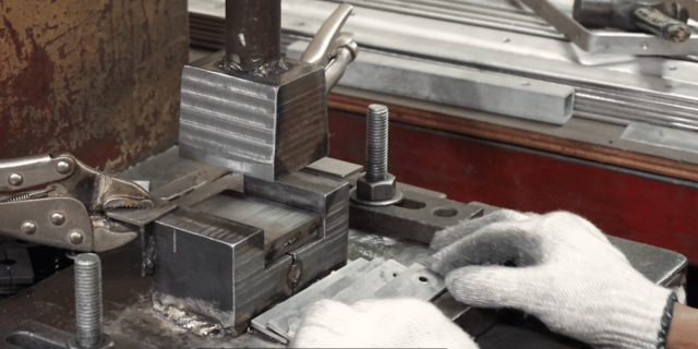
Design and Tooling

Cutting the Metal Sheets

Once the blanking tools have been made, it is possible to stamp out the required shapes from metal sheets. This may take anything from a few hours to 2-3 days, depending on the sizes of the parts and the total quantity of the batch. CNC turret punch presses are used and are fast in operation. For very high production volumes, progressive stamping may be used.

Forming and Welding

The cut sheet metal pieces from the cutting operation are bent and formed on the press brake to get the required 3D shapes. Other parts might also by tack welded together. Small lots can be cut from flat sheets into finished forms within one day. In the case of large quantities, this step is done within one week at most is done at most.

Finishing

After being formed into the required parts, the sheet metal parts may be degreased and painted or coated as needed for the intended application of the product. This may entail sanding, buffing, or applying powder or wet coat. In many cases, simple finishing, such as cleaning or deburring of small lots, can be done in several hours. The surface coating batches should take about a week on average.

Hardware Addition

The final assembly is done in this section, whereby all additional hardware components not included in the initial build are installed.

Other components, including electronics, wires, motors, and fasteners, are then attached to the sheet metal enclosures and housings to form the end products. For simple products with fewer components, it can take a single day to do the final assembly. The final assembly of simple products with one or two sheet metal and hardware sub-assemblies may take about 3-5 days, while more complex products with many sheet metal and hardware sub-assemblies may take about 1-2 weeks in final assembly.
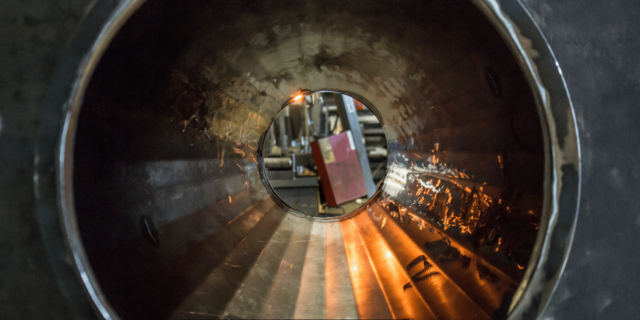
Hardware Addition

Quality Checks

Even at an intermediate stage, checks are made to ensure quality before the parts are transferred to the next level of fabrication. This takes a few hours after each of these main steps. The last process that is conducted on the products is testing and inspection. The units of simple items can take 1-2 days to undergo quality check, while the units of complex assembly components may take 3-5 days for quality check.

Summary

It is possible to produce simple sheet metal parts and products such as brackets and enclosures within one week. As for more detailed products such as machinery housings, furniture, complex medical equipment that comprises several formed parts and sub-assemblies, it may take 3-4 weeks in fabrication.

The sequence is as follows – Design and Tooling (1-2 weeks) > Cutting Metal Sheets (Hours to 3 days) > Forming and Welding (1-7 days) > Finishing (Hours to 1 week) > Final Assembly (1-2 weeks) along with Quality Assurance after each stage (1-5 days).

The total time is, therefore, the sum of time taken at each of the above-mentioned stages. With regard to simple sheet metal products, the total fabrication cycle may take between 1 to 2 weeks. The most complicated assemblies with stringent quality requirements can take about one to two months to complete.

Factors Affecting Time

Some of the critical factors that determine how long sheet metal fabrication takes are:

  • Difficulty in product design
  • The quantity of a product to be produced
  • Number of Forming Operations Required
  • Surface Finish Requirements
  • Hardware and Assembly Integration
  • Quality Standards to be Met
  • Accessibility of Design Data/Tooling and Equipment
  • Manual Operations vs Automation Level

Therefore, with these factors being optimized, sheet metal fabricators can reduce the fabrication time and supply products to the end user faster. Implementing newer technologies like CNC machines, 3D printing for tooling, and the integration of CAD/CAM software also aids in faster turnaround time on sheet metal products.

Conclusion

The sheet metal fabrication process involves cutting, forming, welding, finishing, and assembly operations, which may take a few days to a few weeks, depending on the product type, production quantities, and quality standards required. Basic structures can be achieved in 1-2 weeks, while intricate parts and assemblies can take up to 1-2 months. Through the proper choice of materials, fabrication processes, and fabrication resources, the fabricators can minimize the time taken to manufacture in order to be competitive.

August 20, 2024
Metal-Fabricator-1280x640.png

To be precise, choosing the right metal fabricator for the job also plays a vital role in determining the total costs. An efficient and experienced fabricator has the tools and abilities to do the job at a cheaper price while at the same time delivering quality work and avoiding wastage.

Here are four of the most effective ways a good metal fabrication partner can save you money on your next project:

1. Advanced Technology and Equipment

Using new and advanced technologies in metal fabrication requires skilled metal workers to increase efficiency and reduce material usage. Some cost-saving advancements that your fabricator may utilize include:

– Computer-Aided Design (CAD) Software: Digital design files help to better determine the amount of material that is necessary and take less time for engineering. Compared to hand drawing, there are a few mistakes as well.

Technology and Equipment

– CNC Machines: Computer numerical control equipment provides quicker and automated fabrication of components such as custom steel parts and metal structures. Their precision also enables them to avoid the wastage of materials due to poor cutting.

– Inventory Tracking Systems: Getting detailed information about stock and orders helps avoid buying large amounts of material that are not needed in subsequent jobs. It also restricts the charges for same-day delivery of components in case of a shortage in the usual timeframe.

Advanced technology provides metal fabricators with better tools than those of their counterparts and this allows them to offer their clients better prices through time and material costs reduction.

2. Strategic Material Purchasing

New metal fabrication shops, however, source their metals through retail channels while established metal fabrication shops have wholesaler agreements and long-term supplies contracts with metal suppliers. The fact that their order volumes are large enough also allows them to buy all the necessary materials at cheaper prices. They can then offer those discounts to their customers.

Moreover, people who purchase at these metal fabrication facilities learn that it is always expensive to buy more than what is required on the job. One cannot afford to be charged for excess material that may not even be used in any of the customer projects. This avoids over purchasing from their preferred metal suppliers and helps to manage the overall job costs.

3. Qualified manpower and work-flow

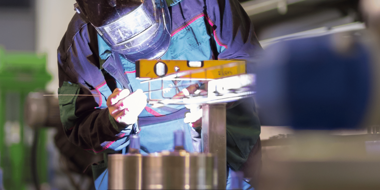
One of the most important but frequently neglected services that specialists in the metal fabrication industry provide is production optimization. It is essential because experienced and well-trained metal workers capable of handling complicated metalwork tasks can do them efficiently and with minimal overhead expenses.

For instance, a professional welder understands how to locate all welds on a structure in a way that will help reduce time. Or a metal fabricator may have current tooling built to rapidly bend specific component shapes for a particular fabrication. Such measures are some of the uncomplicated changes that enhance overall fabrication, decreasing man-hours and overhead expenses.

Similarly, well-trained personnel also result in reduced rework and scrap loss. This awareness of machines and materials makes them avoid costly mistakes that would otherwise be incurred for non-value-added services to customers. By focusing on such issues as processes and employees’ skills, metal fabricators provide significant cost savings due to their expertise in workforce and production.

Qualified manpower

4. Customization of Orders

Thus, it is advantageous to work with a capable, flexible metal fabrication shop since they can bend orders to fit the specific needs of the project and the amount of money one is willing to spend. It is for this reason that an ideal fabricator should be able to take time and work with the customers individually on how best to approach every job.

Thus custom production runs allow for the purchase of the exact required amounts of material as opposed to having to purchase in the closest standard industry multiple. It is also essential that fabricators construct jigs and even program machines in a way that they manufacture only the necessary parts and not more or less. This keeps the procurement of materials within reasonable limits and does not allow for extra manufacturing processes.

Furthermore, extensive cooperation with professional fabricators often brings new solutions to the production process. For instance, altering some steel shapes or certain types of welding may maintain strength and at the same time consume less steel. Your fabricator may also recommend another metal or after-production that results in the same end product but at a cheaper cost.

Utilizing these custom fabrication opportunities enables metal fabricators to minimize the costs throughout the entire process while providing parts and components to your required standards.

The Bottom Line

In order to achieve the best result for your next custom metal fabrication project, work with a reliable metal fabricator who will use only the latest technologies and tools, has a well-trained staff, and allows for a great variety of options when placing an order. Their abilities and knowledge of optimizing the manufacturing process of metals will ensure that your project is on track and within your budget.

Also, when quoting, ensure you are as transparent as possible with fabricators. Document the fine prints and targets of your project. An experienced fabricator will advise on how they can make the project cheaper, yet come up with a quality metal product that suits your needs. Suppose the advice of the architect and the construction engineers is followed. In that case, it will ensure that the cost of expenses such as over purchased materials and other inefficiencies that may be incurred later are well controlled.


August 10, 2024
Materials-Suitable-and-Unsuitable-for-Laser-Cutting-2-1280x640.png

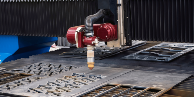
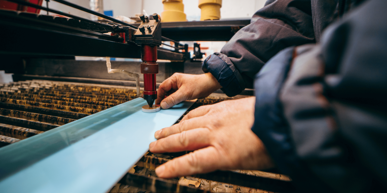
Laser cutting is a form of fabrication that uses a laser to cut through materials. The focused laser beam deposits heat and removes the material in the cutting area, providing a clean and accurate edge. Selecting appropriate materials is very important when it comes to laser cutting. The material characteristics determine the accuracy of the cut and the sharpness of the edges. This article describes different materials that can be laser cut and which aspects make them suitable or unsuitable for this process.

Appropriate Material for Laser Cutting

Many materials can be quickly and with excellent precision cut with the help of laser cutting technology.

Material for Laser Cutting

The most commonly laser-cut materials include:

Metals

– Stainless Steel: Laser cutting is well suited to stainless steel due to its non-corrosive nature and high-quality surface finish. It provides a better edge finish and very sharp cutting. The fact that the material to be cut is highly reflective also makes cutting take a shorter time.

– Carbon Steel: Carbon steel, however, can also be laser cut, though it may need more energy than stainless steel. It offers a good edge quality.

– Aluminium: Laser cutting is a perfect process for cutting Aluminum. It uses less electricity to operate and has a lower melting point that enables faster and cleaner cuts.

– Titanium: While cutting titanium, high power is needed for laser cutting, giving very high edge quality cuts.

– Brass and Copper: Brass and copper materials are thermally conductive and enable accurate and thin laser cutting. The cut edge has high reactivity with oxygen; it should be cleared immediately after cutting has been done.

Plastics

 Acrylic: Laser cutting is also ideal for acrylic because of the material’s characteristics. It evaporates with little residue, and has a flame polished edge to it.

 Polycarbonate: It will not melt around the cut lines or become stiff and gummy, making it easy to cut through polycarbonate. It provides a high and accurate finish cutting.

Wood and Paper

– Plywood: Plywood is also one of the best materials that can be worked on through laser cutting. It barks the wood somewhat, but it can carve more detailed designs precisely.

Cardboard and Paper: Thin sheet materials like cardboard, paper, etc. can also be cut using laser, for instance, for the creation of packaging mock-ups and models.

Fabrics

– Natural Fabrics: Garments such as, cotton, wool, leather, etc. can be easily cut by laser. Low melting point materials such as synthetic material polyester are not appropriate.

Conditions that make a material fit for laser cutting.

material laser cutting

The suitability of a material for laser cutting depends on factors like:

– Composition: The uniform density and nature of plastics and woods are preferable to others since they have a constant and consistent nature when cut.

– Melting Point: Substances that have low melting points change to vapor when the laser broils them. This results in clean and accurate incisions as opposed to the edges melting into each other and becoming blurred.

– Flammability: Highly flammable substances such as wood or plastics do not yield good cut quality as materials that are hard to ignite, like metals.

– Reflectivity: In other words, some materials such as aluminium and copper are reflective, hence they are easier to cut than other non-reflective materials such as acrylic.

Thickness: Laser cutting is more suitable for thin sheets. Thick sheets may need to be passed through the cutter a number of times or precut in some way.

What are the types of material that are not suitable for Laser Cutting?

Although lasers are versatile and can cut through virtually any type of material, there are certain materials that are either more challenging to cut with a laser or should not be cut with lasers.

These include:

Metals

 Tool Steel: Tool steels are usually heat treated and are too complex to result in clean laser cutting. Cuts have bad edge condition with thermal cracks.

– Lead: Lead is a relatively low melting point material and it decomposes under influence of laser cutting rather than evaporates. This results in rough edges with debris.

Plastics

– PVC: Yet, PVC releases toxic chlorine gas when heated or when burned, which has far-reaching environmental implications. This makes PVC a risky material for indoor laser cutting.

– Nylon: Nylon undergoes melting and burning instead of vaporization during laser cutting, and for this reason does not offer quality edges.

Other Materials

– Glass: The material of glass undergoes thermal shock and stress of laser cutting and as a result cracks. The cut edge is irregular and not a clean edge.

– Ceramics: Ceramics do not melt when exposed to lasers, meaning that there is restricted material removal. They also appear along the cut lines.

Composite Materials: When cutting through non-homogenous composites with multiple layers of different materials, the composite may delaminate or crack.

Conditions That Make a Material Inadaptable for Laser Cutting

Properties that make materials perform poorly during laser cutting include:

– Thermal Cracking: Materials such as tool steel and glass tend to crack when subjected to heat, such as thermal cutting, and degrade during laser cutting rather than vaporizing.

– Toxic/Irritant Byproducts: Some of the products such as PVC emit hazardous gases when exposed to heat. These toxic byproducts make the materials dangerous significantly when cutting them within the enclosed space.

– Excessive Melting: Substances that soften but do not vaporize at the laser interface leave behind a poor-quality edge with congealed material and debris buildup.

– Inhomogeneous Composition: Different density, composition and layers structure of composite materials result in low quality and uneven laser cut.

Conclusion

According to the type of laser used, it is possible to cut metals, plastics, fabrics, and many other materials with high precision. Precision and cut quality depend on the use of materials that suit the machine in terms of the thermal characteristics, melting points, and the mixture used in the material. The materials that should not be used for laser cutting include those that are likely to crack, melt, or emit toxic fumes for the sake of safety and efficiency. With these aspects in mind, the capability of laser cutting can be harnessed for fast construction.


July 18, 2024
Laser-Cutters-1280x640.png

Introduction

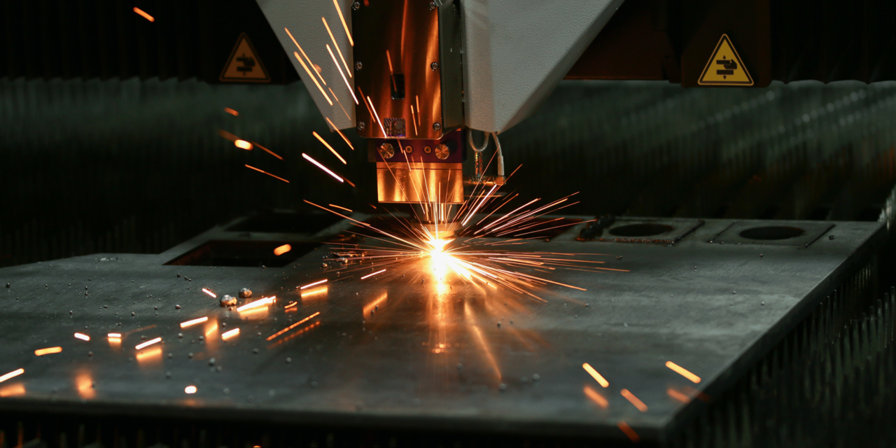
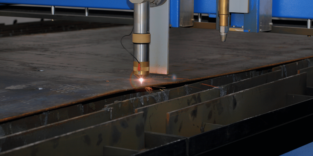
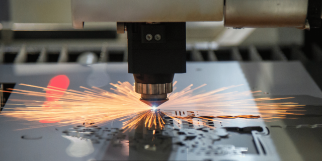
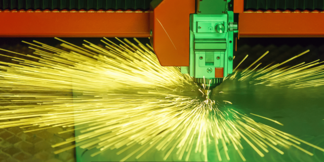
Laser cutting is one of the thermal fabrication processes that involves using laser beams to cut or melt materials. The concentrated light wave sears, fuses, boils, or discharges away material to carve complex shapes and graphics. Since laser cutters have such high accuracy and speed, they can be widely used in many industries such as manufacturing, construction, aerospace, automotive, etc.

Some of the current laser cutters have different laser technologies, power, control, moving systems, and so on. To help you envisage this, this article will give a brief overview of the standard laser cutters.

CO2 Laser Cutters

CO2 laser cutters are currently used as the premier laser cutters in the market today. As the name implies, they employ a sealed CO2 carbon dioxide gas as the active medium within a CO2 laser chamber to emit an Infrared laser beam.

The CO2 laser generator is made up of a cylinder that has been provided with a CO2 gas mixture, and when a high voltage is applied, the mixture emits an infrared light of wavelength 10. 6 microns. This infrared laser light is then focused through lenses on the workpiece placed on the laser bed to melt or vaporize the material.

CO2 Laser Cutters

In fact, CO2 laser cutters are machines used to cut wood, plastics, textiles, acrylic, leather, and many others. It can only shave through material not more than 1 inch thick, depending on the capacity. These lasers provide excellent edge quality and still generate neat, accurate cuts in a very short period.

Joint CO2 laser cutters:

– Low power (10-100 watts) – practical for engraving and thin materials such as wood or leather.

– Medium power (100-500 watts) for higher power density, which can create thicker materials up to 0. 25 inches.

– High power (500-1500 + watts) –For cutting up to 1 inch material

Fiber Lasers

Fiber laser cutters utilize glass fiber optic cables with rare earth, such as ytterbium, neodymium, and erbium, to create the beam. The fiber cable is then filled with the diodes to stimulate the active medium and emit infrared light at a wavelength of about 1. 05 microns

In general, CO2 lasers are less efficient and use more energy, while fiber lasers have better beam quality. However they encompass a more limited selection of materials like metals and some plastics.

Key benefits include:

– Higher precision cutting

– Faster cutting speeds

– Compact size and portable

– Lower running costs

– Cutting materials such as copper, brass, aluminum, etc, which are highly reflective, is possible with ease.

Fiber laser standards of output power can be between 100 watts and 6 kilowatts used for industrial purposes.

Fiber Lasers

Diode Lasers

Diode laser cutters utilize semiconductor diodes that emit high-intensity laser beams within the visible and infrared spectrums upon the application of current. They work in a fashion analogous to a light-emitting diode (LED).

Certain benefits pertaining to the diode lasers include size, wall plug efficiency, life span, and cost. However, there are disadvantages in their beam power, and the quality of the beam is not very high either. Diode lasers are best utilized in low power operations such as welding of plastics, soldering, cladding, etc.

These machines can cut up to a capacity of 0. of 02 inch thickness. Output power control is mainly in the range of ten to one hundred watts.

Other Types

Some other niche laser-cutting technologies include:

Picosecond Lasers:

Create pulses of concise duration with a range of picoseconds for exemplary kerfing processes necessary for cutting fragile material less than 10 µm and drilling tiny holes less than 500 µm. Popular among the electronics and semiconductor industries.

Ultraviolet Lasers:

It uses wavelengths in the UV range, such as excimer lasers at 248 or 308 nm. Enables slicing of a wide variety of products without adverse effects from thermal damages for cases where the accuracy of results is of utmost importance.

Green Lasers:

Wavelengths were doubled in frequency, and infrared was converted to visible green light at 532 nm. This applies to the delicate substrates where heat impact must be addressed.

Conclusion

This means that the laser cutters come in all sizes and capabilities based on power, levels of detail, possible material, speed, and cost. The most common types of laser cutters that are used include the CO2 and fiber lasers, which appear to provide the best blend of performance and functionality, which are requisite for most uses. Choosing the right laser-cutting equipment is crucial based on the cutting requirement and the type of material to produce good outcomes.


July 11, 2024
Fiber-vs.-CO2-Lasers-1-1280x640.png

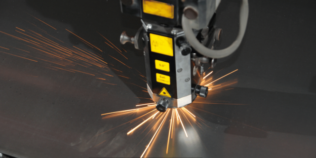
The CO2 and fiber lasers are used predominantly in various industrial sectors for cutting, welding, drilling, and other operations. Each has its strengths and weaknesses concerning things like power, accuracy, costs of running, and maintenance, among other things. This article includes a comparison between the fiber and CO2 lasers.

Power Output

– Fiber Lasers

Fiber lasers can provide output power of 100W up to 50000kW. The output power has also improved in recent years due to constant technological improvements. Today, primary industrial machines use 30kW fiber lasers.

Fiber Lasers

– CO2 Lasers 

CO2 lasers are available in the power range of 100W to 25kW despite being large-scale lasers. While 50kW CO2 lasers are also produced, they are relatively more difficult and costly to manufacture than the other two types of lasers. They are also known to have higher power density than fiber lasers, with some CO2 lasers being even more potent than fiber lasers in some cases.

Comparison

However, as we have seen, fiber lasers deliver less power than CO2 lasers in a given bandwidth, although the difference is narrowing with new high-power fiber laser models. As much as used in industrial applications of up to 25kW, both lasers can provide adequate power.

Precision and Focus ability

– Fiber Lasers

Fiber lasers employ glass fiber with small core diameters, which enables small spot size and more precision. The spot sizes can be as small as 5 microns and, therefore, very useful in fine cutting, welding, and micro-machining.

– CO2 Lasers

It is typically advised that CO2 lasers may produce spot sizes in the range of 50 to 100 microns. However, that is possible at small spot sizes, which need complicated optics and adaption systems. As for the cutting performance, the simple CO2 lasers are not as accurate as the fiber lasers.

– Comparison 

In comparison to beam quality and spot size, fiber lasers are superior to CO2 lasers. As a result, they are ideal for use in applications that need accuracy, such as when cutting small holes or when creating delicate patterns.

Operating Costs

– Fiber Lasers 

CO2 lasers have low EEo efficiency in the range of 10-15%, while fiber lasers have an efficiency of 30%. This can considerably cut down the total cost of running the business, especially in relation to electric power consumption. They also have long life spans, and little maintenance is required when compared to other types of fiber lasers.

– CO2 Lasers

General expenses of CO2 lasers are also high because their electrical to-light conversion is low; they use lasing gases, and they need frequent replacement of discharge tubes. The costs are incurred over years and therefore they are not all that cost-effective.

– Comparison

Cost of running a fiber laser system is much cheaper than that of a CO2 laser. Fiber lasers require less energy and less maintenance than other lasers.

Cutting Capabilities

– Fiber Lasers

Fiber lasers are versatile and can cut materials such as mild steel, stainless steel, aluminum, brass, and many others. Cutting with a fiber laser beam is precise and can meet strict tolerance. They can also successfully apply any reflective metals.

– CO2 Lasers

Furthermore, CO2 lasers are also able to cut all types of metals, including mild steel and aluminum. The cut quality is often slightly inferior to that of fiber lasers but usually is within the acceptable standard for most operations.

CO2 Lasers

– Comparison

Putting into consideration the cutting aspect of industrial metals, both fiber and CO2 lasers are versatile in their operations. A fiber laser is capable of producing a higher quality cut. Also, it can handle materials which are reflective in nature. Interestingly, CO2 laser cutting is still sufficient for tasks that do not involve a level of precision beyond that of a few microns.

Maintenance Requirements

– Fiber Lasers

More diode pumps, fibers and optic components of fiber lasers are known to last for tens of thousands of hours with minimal maintenance. The downtime for fiber laser is far less than that in other laser machines.

– CO2 Lasers

CO2 lasers involve using such expendable parts as a discharge tube, gases and rf power supplies. They incorporate cleaning of optics. This translates into higher maintenance requirements than fiber lasers used in other applications.

– Comparison

So, in the context of this comparative review, it can be stated that fiber lasers have substantial practical benefits to CO2 lasers when it comes to reliability and the necessity of maintenance.

Conclusion

In conclusion, although high power CO2 lasers have some merits, fiber lasers are becoming more popular than high power CO2 lasers in many industrial applications. Since fiber laser cutting systems can produce higher beam quality with comparably smaller system configurations, they are the ideal systems to meet metal fabrication requirements. They are also cheaper to run than other trains and this make them affordable in the long run. It is anticipated that more advantageous applications will be unveiled in the future as the technology of fiber lasers advances.


May 25, 2024
8-Welding-System-Anti-Aging-Tips-1280x640.png

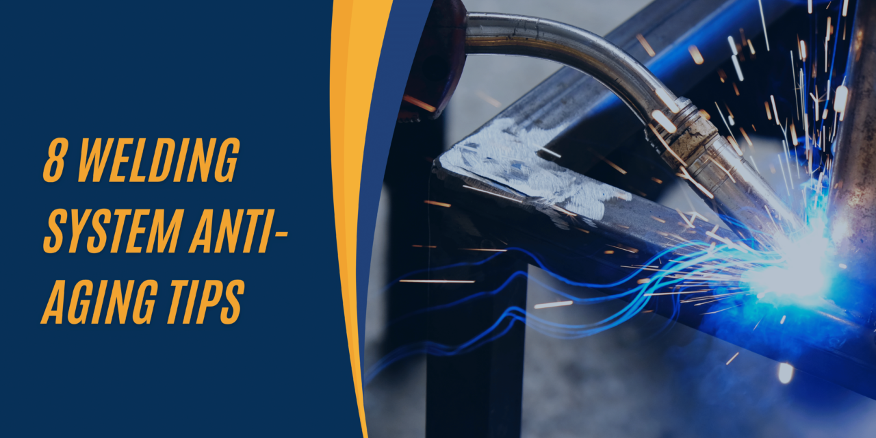
These eight welding system anti-aging strategies can be a practical implementation in technology development for the future.

Welding equipment is exposed to the temperature, spatter, mechanical overload, and strain during ordinary usage. The mentioned factors can seriously impact the efficiency of your welding system within no time. Regular preventative maintenance and care will protect and prolong the life cycle of your welding equipment as well as grounds for premature breakdowns and failures. Here are eight tips to keep your welding system operating like new for longer: Here are eight tips to keep your welding system operating like new for longer:

Perform Regular Cleanings

* The dirty welding torch and wire feed system need to be wiped regularly with compressed air and a wire brush to remove rust from it.

* Swept out any debris hidden in cable lines duct

* Wipe with a clean cloth to remove stains from the outside to avoid residue forming.

Perform Regular Cleanings

Replace Consumable Parts

* Follow the manufacturer’s guidelines in terms of the items to be replaced at regular intervals in order to limit the effects of wear and ensure good welding performance.

* Perform drive roll inspections when grooves are present, or the rolls are no longer able to control the wire production.

* Replace cables if cores become visible through the dielectric or insulation frays around it.

Lubricate Moving Parts

* In order to enhance the welding areas with sliding parts, use a grease designed especially for welding parts on these surfaces.

* Lubricate wire guide rods, drives, and bearings, as well as tensioner rolls.

* Greasing torch necks with an appropriate lubrication agent to ease their articulations.

Protect Gas Hoses and Regulators

* For gas hoses, try hanging them vertically or coiling them loosely when not using them, thus preventing the bending of pipelines.

*Make sure that hoses and regulators are clear from sparks, spatter, and open flames during welding

* Therefore, it contributes to frequent checking of the existence of leaks and quick replacement of hoses or regulators that are in bad shape.

Monitor Cooling Systems

* For water-cooled torches, investigate another step of hoses and tubes for cracks or holes and change immediately if something is found.

* According to the manufacturer’s recommendations, use up-to-date procedures to drain, flush, and refill coolant.

* Make sure that coolant flow stays uninterrupted and offers adequate cooling.

Inspect Power Connections

* Make sure you look for hot plugs, sockets, and links in all locations.

* Get rid of the looseness of the connections quickly so that the arced damage can be avoided.

* If the male plugs are melted or deteriorated, change them to new electrodes.

Inspect Power Connections

Store Properly When Not in Use

* Wrap the welding machine, wire feeder, and all the auxiliary equipment under the sheltered with the cover when not welding.

* Hand welding kits, cables, lines and guns upwards on wall hooks for an easier access.

Keep all items in unique places free of moisture, terrible shocks and close to environmental temperature. Make sure that they are safe from the effects of vibration and stomping.

Schedule Preventative Maintenance

* Organize regular maintenance slots based on documented work hours.

*Qualified staff can competently diagnose and carry out comprehensive inspections and part replacements.

* Preventing maintenance ensures safety, increases the number of working years, and helps avoid unplanned stops.

Performing these simple cleanups, checks, and maintenance of your welding equipment requires little time or energy yet roundabout short-term benefits. Your weldment remains alternatively longer life, do the job better, and just need repairs less when you are ready to use system maintenance. You can save time and money by focusing on some easy anti-corrosion measures now so that you can keep all your welding machinery functioning well for many years.


May 15, 2024
Fabrication-Welding-Service.png

Introduction

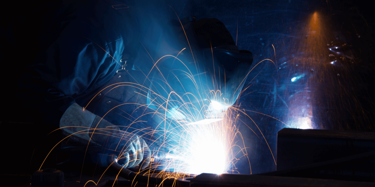
Industrial metal fabrication for the machinery that help assemble metal components to make large structures – or overall products. In the majority of fabrication projects, welding is a very crucial operation, and there are numerous welding technologies concurrently existing in the industrial applications; each one is being used for a specific purpose. Here, the article will briefly describe the five most prevalent types of welding that are commonly requested in industrial fabrication.

MIG Welding

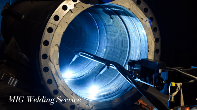
MIG(Metal Inert Gas) welding or GMAW (Gas Metal Arc Welding) is one of the most common as well as very flexible types of welding techniques used in welding industrial fabrication. It includes a replaceable wire electrode that slides through a welding torch also accompanied by an inert gas (shielding) that creates the arc for welding. Some of the benefits of MIG welding include: Some of the benefits of MIG welding include:

High Deposition Rates: You have to use much higher heat and speed than the processes, say, arc welding, for instance. This improves productivity.

Ease of Use: MIG welding is more accessible to acquire and employ as compared to other welding types.

MIG Welding

Versatility: Welding various components like thin sheets and heavy pieces can be done smoothly with the same MIG welder. Its suitability for working with several metals, such as mild steel, stainless steel, and aluminum, cannot be denied.

As a result, MIG welding is used in the production of spare parts, storage tanks, pipeline systems, pipes, and structural frames.

TIG Welding

TIG (Tungsten Inert Gas) welding relies on a non-consumable tungsten electrode with an inert shielding gas to generate the arc. Some benefits of TIG welding: TIG (Tungsten Inert Gas) welding relies on a non-consumable tungsten electrode with an inert shielding gas to create the arc. Some benefits of TIG welding:

High-Quality Welds: High-efficiency TIG (Tungsten Inert Gas) allows for the formation of pure, solid, and uniform welds with excellent metallurgical properties. This is going to be fundamentally important, especially for critical things.

Ideal for Thin and Difficult Materials: The narrow heat beam gives you opportunity to weld stainless steel, aluminum, magnesium, copper and metals that are difficult to work with as thin plane.

Precise Control: In comparison to other welding process type, TIG offers welder a better control over the welding variables thus resulting in very precise welds.

The improved control and tacking ability are vital reasons why TIG welding is widely used in the high-end fabrication of aircrafts, spaceships, nuclear components, bicycle frames, and precision medical apparatus are only but a few examples.

Stick Welding

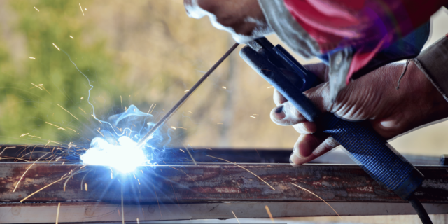
In shielded metal arc welding (sticking weld), the flux coated consumable electrode is used for the production of the weld. Benefits include:

Portability: The cost of the stick welding machines and portability make them a preferred option. In addition, they allow you to work indoors and outdoors as opposed to MIG/TIG alternative.

Versatility: You’ll be exposed to welding many types of iron and non-iron metals using different single or multi-component electrodes. When compared with stainless steel, high carbon steels and nickel alloys can all be stick welded or arc welded.

Minimal Surface Preparation: Stick welding can be used to weld joints in which a lot of oxides, paint and dirt are present as for other welding processes. A rougher surface than average comes often is enough.

Consequently, stick welding is still a top choice, because of its favorable conditions, in the fields of industrial fabrication, involving structural steels, storage tanks, fixing machineries, repair and maintenance applications among others.

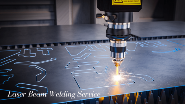
Laser Beam Welding

The focused high-power energy of a coherent laser beam is concentrated on a tiny area of the parts to be bonded. Benefits are:

Extreme Precision: Laser welding is narrow and deep within the competence of 0.5mm without inferiority to other methods for high precision.

Minimal Heat Input: The laser energy is practically absorbed at a small part which is why heat distortion of component is not an issue.

High Speed: The speed of laser welding can be achieved at 100 m/min or more and even more, which is highly far outstripping the other welding techniques.

Due to the mentioned features, the laser welding now becomes an essential tool for manufacturing of medical items, electronics, batteries, parts with the necessity to have a precise, clean and narrow seam.

Laser Beam Welding

Flux-Cored Welding

Flux-cored welding is a very versatile welding process, and it is widely used in many industrial fabrication areas. It is like MIG welding except it uses a wire electrode that is filled with flux instead of a solid wire. The flux protects the weld pool by supplying a gas shield and slag to protect it from contamination in the atmosphere.

Flux-cored welding has a number of advantages for the industrial fabrication process, which implies. It gives a high deposition speed which means that welding is done faster and more efficiently. It can be also used for welding thick materials and it can be performed in any position. Flux-cored welding is another type of welding that is beneficial in outdoor and windy conditions because the flux offers better covering and protection against atmospheric elements.

Conclusion

Lastly, the MIG, TIG, Stick, Flux-Cored and laser welding techniques are the critical welding technologies that cater to the industrial manufacturing sector. The correct welding method is possibly to do with variables being joint design, material type of base, equipment cost requirements and performance expectations as well as other considerations. A description of standard industrial welding methods and their individual advantages can be beneficial for the fabricators to pick the most suitable one according to their specific needs of production.


April 25, 2024
Impact-of-3D-Modeling-in-Agricultural-Engineering-1280x721.png

Technology has been a very influential factor in the reshaping of many industries and agriculture is no different. The need for green farming that is sustainable and efficient has created a niche for agricultural engineering as an indispensable field in modern farming today. One technology that has become popular today is 3D modeling, which is also known as three-dimensional modeling. Through the use of 3D modeling where physical objects or environments are digitally created, agricultural engineers have revolutionized the design, planning, and management of farms.

The Benefits of 3D Modeling in Agricultural Engineering

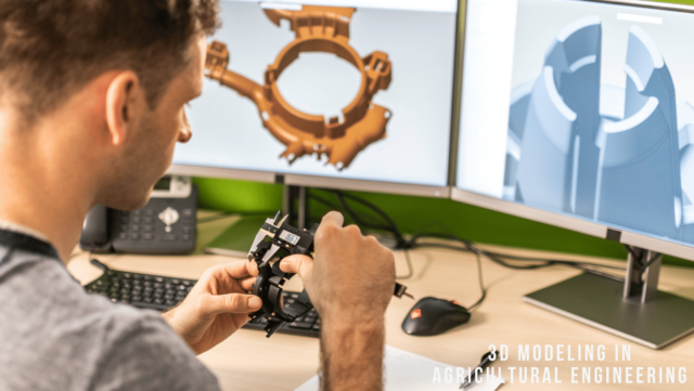
One of the crucial benefits of 3D modeling in agricultural engineering is the provision of a more precise display of design ideas. In a traditional design method, drawings and blueprints are often two dimensional, which can be hard to get a grasp of for non-experts. But 3D modeling enables to design models that are realistic and interactive, and therefore stakeholders are able to see what the product will look like with accuracy. This enlarged visualization helps in better interaction and communication amongst team members, thus the decision making processes become more effective and efficient.

3D Modeling Engineering

Virtual models will enable engineers to run various design iterations and to assess their viability in a virtual environment before committing to them in the real world. It is through this cyclical approach that we save both time and resources by recognizing problems or areas of improvement at the initial stage. Another advantage of 3D modeling is the fact that it allows engineers to simulate different scenarios, like changes in weather or crops growth pattern, hence they are able to make their designs as efficient as possible.

How 3D Modeling is Revolutionizing Farm Design and Planning

The application of 3D modeling in farm designing and planning has been a game-changer for the agricultural engineers, making them change how they work. The application of such technology can be seen in the case of irrigation systems design. Engineers can quite precisely assess the best placement of irrigation infrastructure, including pipes and sprinklers, by constructing virtual models of the farm and its physical features. Through this, the water is allocated efficiently, hence no wastage, and the most yield is achieved.

Through the development of virtual models of barns, silos or greenhouses, engineers can perfect their designs for flow of work and spacing. It enables farmers to use their available land maximally and run the farm in a proper way.

The Role of 3D Printing in Agricultural Engineering

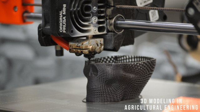
While 3D modelling has considerably transformed the design and planning processes of agricultural engineering, 3D printing has come up as a supplementary technology which is also equipped with a variety of applications. 3D printing (additive manufacturing) is a type of manufacturing process which fabricates a physical part by adding layers of materials based on a digital model.

3D printing can be applied to different areas in agro-engineering. On the other hand, it may be employed to fabricate new parts that do not exist already in the context of machinery or equipment. Alternatively, engineers are able to fabricate and print the parts needed in a short period of time which is faster and takes less money than the traditional manufacturing methods. This decreases the time of downtime and provides a continuous workflow even when the farming operations are underway.

3D printing provides the possibility of producing complicated geometry or prototypes that would be difficult to make with the help of traditional methods. An example of such is engineers manufacturing and printing intricate irrigation nozzles and specialized sensors that enhance precision agriculture practices. This degree of individualization gives the farmers the ability to customize their tools according to their needs and, consequently, improving efficiency and productivity.

The Use of 3D Modeling in Precision Agriculture

At its core, precision agriculture is a method that employs technology to improve farming efficiency and to maximize crop production while at the same time minimizing production inputs. It is a process of gathering data from different sources, like sensors, drones, and satellite imagery, and then using this information to determine the best course of crop management.

3D modeling has great significance when it comes to precision agriculture because it serves as a visual representation of the farm and its features. Through the interconnection of different data sources into one virtual model, engineers can analyze and interpret the collected information more efficiently. For instance, they can map the satellite images on the 3D model to find the spots in the farm that need extra care, such as the spots that need more nutrients or the ones that are infested with pests.

The Impact of 3D Modeling on Crop Production and Management

Although 3D crop model is being applied in crop production and management, this technology has revolutionized the approach farmers take to their work. One example of this is the determination of a planting pattern in the process of planning and management. This can be achieved by developing virtual prototypes of the farm and its relief, which will help farmers to choose the right planning strategy for the most efficient use of the fields. They can assess things like solar radiation, soil type, or water conditions and decide on which crops to grow at which location. At this degree of accuracy, each plant will receive all vital resources for the best possible growth. This in turn leads to increased yield of the crops.

Crop Production

Also, 3D model is used to observe and control the crops health. Via data integration from sensors or drones into the virtual model, the farmer can locate the parts of the farm that need to be looked into, like the nutrient deficiencies or diseases outbreaks. This implies that the application of nutrients or pesticides is only done in the required areas, which leads to cost reduction and the reduction of environmental impact.

The Future of Agricultural Engineering with 3D Modeling

The range of 3D model applications in agricultural engineering is quite broad and progresses due to the continuous development of technologies. We will witness more and more use of 3D modeling tools and applications in agriculture as technology continues to progress and become cheaper.

An aspect with a great potential is the utilization of Virtual Reality (VR) and augmented reality (AR) in agricultural engineering. Through the fusion of 3D modeling with VR or AR technologies, engineers can design interactive activities where users can experience a virtual farm scenario. The said can be very useful for training purposes or for demonstrating design ideas to the stakeholders.


April 15, 2024
Industrial-Automation-Implementation-1280x721.png

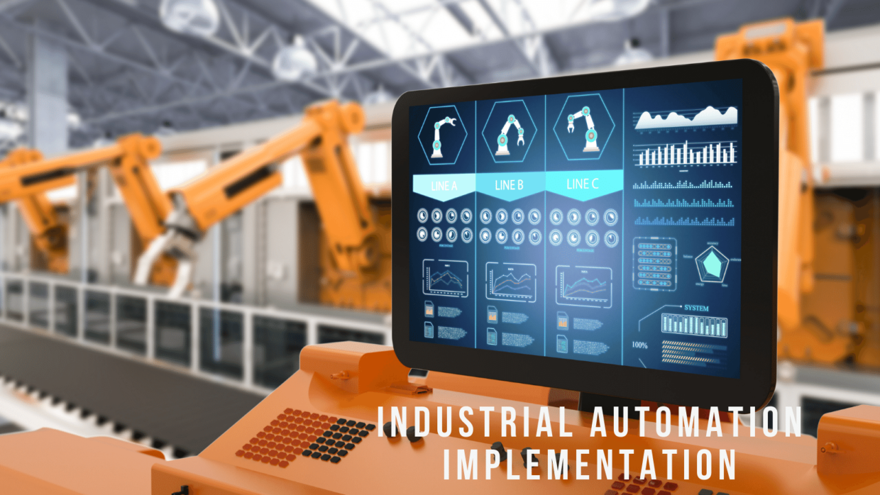
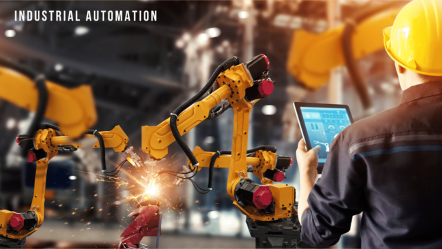
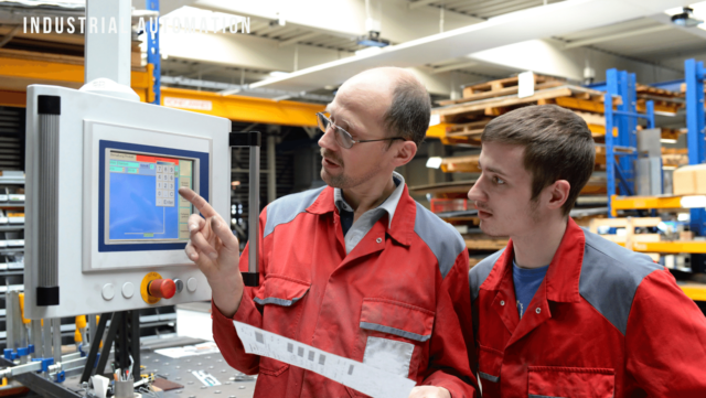
Industrial automation is the utilization of technology like computers and control systems to automate production processes and operations. Onboarding hardware and software components in a system creates an environment that is simple to operate and increases productivity and efficiency. The concept of industrial automation was originated in the early 20th century. In the past few years, the competition among the countries the world over has reached its peak because of technological advancements and global market competition.

Benefits of Industrial Automation

Industrial automation, through its production and efficiency powers, increases productivity and effectiveness. Manufacturing could be accelerated and productivity may be increased by replacing the tedious jobs with robots. This is a source of increased production and hence, organizations can meet the clients’ demands.

Industrial Automation

The application of industrial automation is a quality booster. Automation systems are better in terms of precision and accuracy than humans, and hence they drastically reduce the numbers of errors and flaws. This leads to producing best products that can exceed clients standard.

Common Challenges in Industrial Automation Implementation

Industrial automation provides a lot of advantages but also is a complicated process. Employee change aversion is the well-known phenomenon. Automation often brings about changes in the way tasks are performed and who is responsible for them, which may lead to the resistance of the affected people and redundancies. To overcome resentment, the organizations should focus on the benefits of automation and make employees part of automation process.

The lack of recognition of automation technology is another problem. Automation systems might require businesses to have some necessary skills and information. To materialize the plan without a hitch, some organizations may require training or consultants.

Planning Your Industrial Automation Strategy

The need of a well-defined roadmap is obvious as automation in industrial sector is adopted. This has several crucial steps:This has several crucial steps:

Automation can be used in the production process to find areas that can be automated. Consider the tasks that are repeated, take too much of time, or result in errors. They are such a great fit for automation.

The following step is to define the objectives of automation project. Identify your automation goals, they include productivity, quality, or cost reduction. Plan and budget the automation project you are going to implement. Subdivide implementation into stages and provide the essential resources.This will streamline implementation.

Provide automation project participants with respective positions and responsibilities. Describe the actors who will perform design, construction, testing and maintenance activities. Identify the parameters that determine the success of your automation project. Choose KPIs that will go along the objectives. Get familiar with these key indicators and follow them closely to monitor progress and make changes if needed.

Choosing the Right Automation Technology

Industrial automation project success depends on the ability to identify the right automation technology. Automation technologies also include robots, PLCs, and CNCs. Only pick the technology which fits your manufacturing process, not the other way around.

Take into account the technology of automation on the basis of cost, scalability, adaptability, and integration. Compare at least two vendors and suppliers to obtain the best deal for your business. Consider quality, expertise, customer service, and reliability of products.

Testing and prototyping are the main aspects that we take into consideration. Before adopting an automation solution, test and design it to ensure you are getting full value for your money. This eliminates risks and provides that the project is on course.

Integrating Automation with Existing Systems

Automation intergration with current systems is a hard nut to crack. Compatibility of system has to be tackled to avoid the hinder of smooth integration. Integration calls for specification of data management, communication processes and system interfaces.

The implementation of automation with the existing systems also implies data management and integration. Decide on data collection, storage, and sharing techniques. Listen to the given audio and predict the speaker’s next statement: > Aside from the financial impact, the social ramifications of global poverty are equally profound. Plan the data sharing protocols that will provide accurate and timely information.

Communication standards serve as the basis for system integration. Automation technologies may rely on Ethernet, Modbus or Profibus, etc. Ensure that your automation technology is integrated with your systems and operated properly.

A system can be integrated only after completing quality assurance and validation. To make sure the entire system is functioning well, and satisfying you, run tests on it. Ensure consistent achievement of the system’s performance against the approved benchmarks.

Training and Education for Automation Implementation

Automation implementation is the very reason why training and knowledge are necessary. Staffs need to be taught how to manage and maintain automated systems.

Training and education are key to it. Automation technologies are evolving, thus, workers must keep abreast with the latest technologies. Training employees on a frequent basis can help them to gain new skills and to be in step with new technologies. There are three options in training- classroom, job, and online. Define the staff training requirements and select right training methods.

Training and Education

The ultimate objective is to make sure employees gain from training by evaluating the effectiveness of this training. Measure training’s contribution to performance, productivity and job satisfaction in terms of KPIs. Revisit these numbers periodically to find defects in the training programs and make the necessary changes.

Ensuring Safety in Industrial Automation

First of all, I would like to emphasize the importance of security in industrial automation. Workers, equipment, and the process of making need to be protected, which will be done by safety measures.

Risk assessment and management are two indispensable elements of industrial automation safety. Find automation systems threats and formulate methods of their mitigation. Review and revise risk assessment as the technology and processes become available.

It is mandatory to obey the safety regulations. Discover what safety guidelines are in force in your sector or where you are working. For workplace safety, guarantee compliance with these requirements of your automation system.


April 5, 2024
Combatting-Silica-Dust-1280x721.png

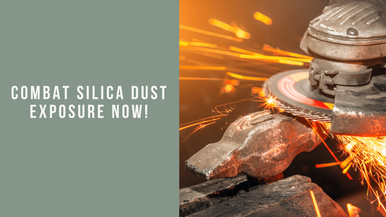
The industrial operations incorporate cutting, grinding, drilling, and breaking the crystalline silica minerals, which in turn generate silica dust. Rocks, sand, and soil, all of them, consist of crystalline silica. Such a situation may result in the production of small silica dust particles, which can be a serious health hazard to workers.

In particular, inhalation of silica dust can have a range of severe health effects, so it should be avoided. Silica dust breathing in can lead to silicosis, lung cancer and COPD. Long-term silica dust exposure is also a cause of the internal disease like renal and autoimmune. Hence, the workers who work in the industries where there are high amounts of silica dust should do their best to lower the exposure to this dust.

Understanding the Health Risks of Silica Dust Exposure

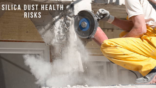
The most likely health hazards of silica dust are respiratory diseases. Breathing in silica particles leads to silicosis, a disease that is irreversible and relentlessly progressive. Inflammation and scarring from these inhaled particles can occur continuously, making it difficult to breathe and hindering lung function. As with the other disease, silicosis has a capacity to kill in the most severe cases.

Silica Dust Health Risks
It is a well-known carcinogen that is classified by the IARC. Silica dust can also give rise to COPD, a chronic disorder that clogs the lungs and prevents air flow from the lungs.

Apart from the respiratory disease, silica dust has been found to be linked with numerous other health issues. Research indicates that long-term silica dust exposure might have a direct impact on the disease progression to chronic kidney disease and end-stage renal disease. In addition, there are studies that suggest that the inhalation of the silica dust might be linked to autoimmune diseases such as rheumatoid arthritis or SLE.

Common Industries and Jobs with High Risk of Silica Dust Exposure

The excessive inhalation of silica dust is typical in some industries and occupations, though. Working in the building industry is the most dangerous job. Hammering, drilling, and chiseling concrete, stone and brick releases silica dust. The danger is contributed to by the fact that mining is associated with the removal and processing of silica crystals.

The hazards of manufacturing units that make glass, ceramics and cement are immense. Sandblasters and workers handling abrasive are highly susceptible to this silica dust. Farm workers who pick crops, dig soil, or handle fertilizers can be exposed to silica dust which is found in soil or agricultural products.

Identifying Sources of Silica Dust in the Workplace

The solution to the problem lies in locating where the silica dust in the workplace originates. The termination of crystalline silica, sandblasting, or handling of dusty materials like sand or dirt are well-known sources. The failure to manage the tools and equipment can lead them to produce much of silica dust.

Routine work place inspections that identify silica dust sources are part of the process. Employers are to grapple with work stations and operations that can result in silica dust and their effects. This can be achieved by watching the work practices, assessing MSDS, and talking to the workers that are directly exposed to silica dust.

Remember that all silica-containing products are not harmful. Risk is a function of the silica concentration, the number of days in the exposure, and exposure frequency, and the protective measures employed. As a result, it is necessary to carry out the risk assessment and the priority setting for each silica dust source.

Best Practices for Minimizing Silica Dust Exposure

Engineering, administrative, and work methods that are combined will help the company to minimize the amount of silica dust in the air. Engineering controls achieve the reduction or elimination of silica dust by changing the design of a workplace or equipment. The methods can be any of the below, such as wet cutting or grinding, local exhaust ventilation, or the use of dust contained procedures.

The management team will develop rules and procedures to cut down the risk of getting infected. Staff rotations, restriction of high-risk activities and provision of safety training can reduce exposure time and hence, the health hazard. Furthermore, enterprises should draw out clear procedures for silica dust cleanup and disposal that will avoid the re-entrainment of dust.

Techniques of work including using the right tools and equipment and wearing protective gear are also important for silica dust reduction. Providing training on equipment use and handling will decrease the amount of dust. For cutting and grinding, you should use either water suppression or vacuum systems to get rid of dust. A good housekeeping should be implemented to ensure that work areas remain clean and free of dust.

Personal Protective Equipment for Silica Dust Protection

Engineering control and work practice are a way to reduce silica dust exposure so that PPE is used only as an additional one. Using PPE alone should not be a measure used. Other control measures should always be in place.

A lot of personal protective equipment (PPE) is able to protect workers from silica dust. N95 and PAPR respirators are the most important gear for removing airborne silica particles. Wear safety glasses or goggles to protect your eyes. Donning coveralls or suits that can be thrown away can help in reducing exposure to silica dust, as well.

Silica Dust Protection

Proper use of PPE is a key to its effectiveness. Workers must learn how to wear and remove PPE, check respiratory protection seals, and store it properly. Another thing is fitting and comfortable PPE and it is also very important because of ill-fitting or uncomfortable equipment, workers are not ready to use it.

Training and Education for Silica Dust Safety

A silica dust safety program should include training and information as its integral elements. Workers who may be exposed to silica dust should be trained to recognize the health hazards, the types of job that can expose them to silica dust, and the control measures and PPE that can be used to mitigate the effects of silica dust.

The training courses need to be developed with how to detect silica dust respiratory disorders, the importance of regular workplace inspection and the methods of lowering silica dust exposure being emphasized. Workers need to know how to use and keep up with respiratory protection and other PPE.

The workforce should go through regular training to be up to date with safety rules. Employers need to provide periodic review and upgrades to control techniques and equipment. Organizations should provide the communication platforms to workers and management so that they can share their views and concern on silica dust safety.


CONTACT DETAILS

Our Company


(905) 643-7710

905 643-7720

info@gfmachineshop.com
WORKING HOURS

HOURS OF OPERATION


Mon – Fri : 8:00 AM – 4:30 PM

Emergency: after hours service is available
GET IN TOUCH

Follow Our Activity