gfmachines, Author at GF Machine Shop LTD. - Page 2 of 4

October 15, 2024
Can-You-Weld-Galvanized-Steel-1280x720.jpg

The steel part protected from corrosion by zinc is known as galvanized steel. This way, the zinc covering protects the steel by acting as a barrier to oxygen and water. Thus, it can be pointed out that galvanized steel is appropriate for use in open air and when corrosion is an issue.

However, the zinc coating poses some complications when welding galvanized steel, as noted below. While welding over the painted surface, the steel gets hot, and zinc vaporizes and comes out in thick white smoke, which includes zinc oxide dust. This fume is destructive health of the welders. Additionally, zinc can become a problem for weld quality unless some action is taken to mitigate it beforehand.

Hazards of Welding Galvanized Steel

Welding Galvanized Steel

Health Hazards

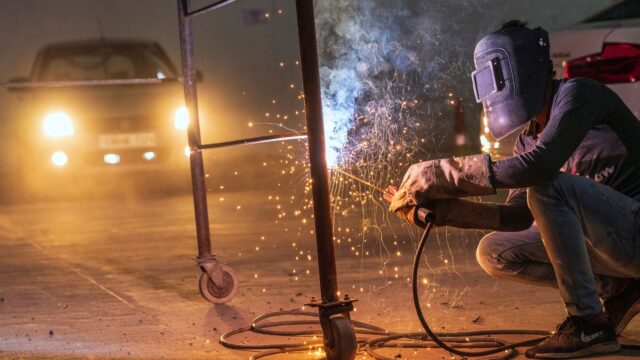
When the galvanized steel is being welded, zinc is apparent as zinc oxides enter a fume state. During welding, this fume appears as intense white smoke and has a solid-like consistency. Respacing of copper and zinc oxide fumes and particulate can result in metal fume fever or zinc shakes.

Metal fume fever causes flu-like symptoms, including:

– Fever, chills, cough
– Fatigue, weakness
– Nausea, vomiting
– Chest pain, metallic taste

Repeated breathing of the Zinc oxide fumes may also cause more severe diseases like bronchitis, pneumonia, and other respiratory diseases. The zinc oxide particulate formed when welding galvanized steel is hazardous as the particles can be quickly drawn into the lungs.

Weld Quality Issues

Other than the health risks, welding over galvanized steel also affects the weld quality if zinc is not well handled.

Issues that may arise include:

– Porosity –The holes in the weld are formed due to the trapped gas and Zinc vapor bubbles. This reduces strength.
– Cracking – the zinc found in the weld is incompatible with weld fusion and metal flow.
– Weak welds – contaminants decrease the strength of the joining area. Welds may fail under stress.
– Zinc embrittlement is a condition whereby if zinc penetrates the weld area, it tends to make steel much more brittle.

These quality issues are attributed to zinc penetration into the weld pool and disturbance of the welding process. Flaws mean that to some extent cracking and porosity result in the formation of bad areas, and reduction of toughness leads to loss of elasticity.

Galvanized Steel Welding Preparation

Steel Welding Preparation

While galvanized steel introduces health and quality risks during welding, there are some techniques for dealing with the zinc coating before welding:

Grind the Zinc Coating Off

If you have an angle grinder or can even buy a particular grinding wheel, it would be pretty easy to grind through the zinc coating along the weld area. This should go at least 1.5-2 inches forward of this point where weld will be done. Reduce the material to shiny metal or steel.

If there are some particles of zinc flakes remained on and around the ground weld area, clean it with a stainless-steel wire wheel brush. This in turn assists in minimizing the chances of getting zinc contamination of the weld.

Utilize Zinc Removing Chemistries

That is why there are particular chemical solutions for the galvanisation, or removing the zinc layer before welding galvanized steel. Almost all contain phosphoric acid, which may be diluted or used in a gel that adheres to verticals.

These chemicals dissolve the zinc coating so as to generate a water-soluble phosphate compound. You clear this with a wipe or rinse, then you get the steel exposed. It is essential to comprehend these zinc removers work along the recommendations provided on the packaging of the products.

Nevertheless, some types of galvanized steel, particularly the coupons, continue to release zinc fumes during welding after applying these removal techniques. It is essential to ensure you have a fume extractor nearby the weld zone to be ready to collect noxious smoke.

Use Let it Cool and Brush Off Slag techniques

When liquid zinc is applied to the occurring galvanized coating, some of it boils off and may take iron particles from the steel with it. The zinc/iron alloy on the steel surface and forms flaky slag.

Remember, if welding galvanized steel, it is advisable that the weld is left to cool and then is wire brushed. It helps clear any slag, if there would have been any accumulation near the weld joint. In case it remains on the weld joint, slag lowers corrosion resistance of the weld joint.

Application of Low Hydrogen fitting material

Utilizing low hydrogen type filler material for welding is highly preferred due to several reasons advertised ahead.

The suitable filler material should also be selected because the material might absorb significant moisture during welding. Two types of electrodes, namely cellulose electrodes and rutile flux core wires, are readily permeable to moisture. When welding over galvanized steel, this will create weld porosity and welding cracks.

Can Welding Galvanized Steel Be Done Safely?

However, welding galvanized steel introduces some of these risks, but it is possible in many situations. However, to use galvanized steel is possible only with certain precautions than standard steel.

In welding proper ventilation along with the use of a respirator also reduces uptake of zinc oxide fumes as they are given off. Last but not least, it is essential to modify technique and employ low-hydrogen filler metals as a response to moisture challenges.

However, if proper preparation of the joints, adequate ventilation and type of electrodes are employed welding of galvanized steel can be difficult and there are many challenges. But there is health risks occasioned by smoke produced from zinc oxide and it may therefore not be advisable to weld galvanized parts by yourself without taking professional help.


October 5, 2024
Can-you-cut-aluminum-with-a-laser-1280x720.jpg

Laser cutting is quickly gaining popularity as an efficient and precise method used to make cuts across the material. Many industries use aluminum because it is light, strong, and corrosion-resistant. Can lasers cut aluminum? In this article, the reader will get a detailed and clear understanding of cutting aluminum using a laser.

How Lasers Cut Materials

Laser cutting

A laser – A concentrated beam of light power

Lasers direct a very high-density, slim stream of light energy to a specific area. This concentrated energy puts the heat intensively and rapidly on any target material, making it melt and vaporize. During the scanning process, the laser beam also maintains a cutting process through ongoing melting and vaporization of the material.

Computer numerical control for accuracy

Today, laser cutting machines are controlled by computer numerical control (CNC) technology to prevent the head of the laser. This enables making immaculate and accurate cuts to even hard-to-shape mass through the material. The thickness, speed, and beam power are variable to establish the proper cutting mechanism for the various forms of material.

Conditions Involving the Process of Cutting Aluminum with Lasers

Material Thickness

Less thick aluminum can be cut with relative speed. The thickness of the aluminum influences the laser cutting in terms of possibility and speed. Some users cut much thinner sheets that are slimmer than ¼ inch, and they need laser power to make the cuts. Thicker blocks require high-power lasers, low cutting speeds, and possibly several passes to complete the cut.

Alloy Composition

The combination of high iron or copper content spikes up the troubles. The cut material melts when subjected to the lasers. It took more laser energy for high iron and copper-containing aluminum alloys to cut because they have a higher boiling point than an alloy with a lower iron and copper content. Pure aluminum grades are more easily vaporized and cut through with lasers than are the alloyed varieties.

Desired Cut Quality

It also means that higher quality cannot simultaneously be associated with lower speed. The inclination of the cut aluminum should ensure that a fine finish of the edges is produced without the laser being rugged. One simply has to reduce the speed at which one is cutting and also fine tune the power and focal distance to get a perfect laser cut edge. The fast-cutting aluminum leads to creation of rough edge.

Cutting Capabilities

It can get you very detailed, very intricate, tiny cuts. In brief, the most significant benefit of laser cutting is making fine cutting edges on the surface of aluminum with precise cuts. It cuts simple figures, combined shapes and contours with great precision and ease, small and complex holes, and slits are simple for a correctly set up laser cutter. The cuts display high edge quality when implemented in an optimal manner.

Limitations

Difficulties arise when the material is a reflective surface, e.g. its responses are given in reverse. An aluminum material has a glossy and reflective characteristic that bounces part of the laser power without cutting the material properly. This reflective nature implies that to energize the metal more power is required as compared to other metals. In addition, if aluminum is not prepared correctly, it turns into oxide when heated during the laser cutting process.

It takes high power to bend a thick aluminum. Aluminum thin sheets can be slit but thick blocks above 1 inch in thick are difficult for most industrial lasers. High powered lasers of few kW or even thousands of watts can gradually cut thicker aluminum blocks. Aluminium has an immense potential for heat dissipation and as the thickness grows it chases the heat away from the cut area.

Summary

  • Lasers soften and evaporate in order to saw through aluminum.
  • Through Computer control, it becomes easy to describe brutal, accurate cuts.
  • Can cut tissue thin sheets, thick blocks have to use special high power lasers.
  • The surface oxidation as well as reflectivity of the material influences the cutting.

When adjusted for optimal cutting speed and appropriate laser power, lasers in cutting the foils of aluminum all the way up to a few inches thick are feasible. For cutting aluminum, it is essential to use laser, as the method has an excellent level of precision and complexity to cutting patterns that cannot be achieved through other means. Laser cutting made at high precision shows new ways to produce various products through aluminum.


September 26, 2024
Fabricate-Sheet-Metal-1280x640.png

Sheet metal work is manufacturing useful products from thin metal by cutting, bending, and joining. Sheet metal is applied in the manufacture of small parts including brackets and enclosures and large structures including airplane wings and automobile bodies. The knowledge of the fundamental concepts of sheet metal work allows makers and hobbyists to fabricate metal parts from a raw material. Here you will be able to read about the main types of sheet metal working and some tips for those who start their journey in this field.

Gather Tools and Materials

The first step is to assemble the necessary tools and supplies. Standard sheet metal fabrication tools include:

Tools and Materials

– Tin snips – sheet metal cut by hand

– Shears are employed in cutting straight lines on thin sheet metal that is also referred to as light gage sheet metal.

– Nibblers – used to cut curves and holes in sheet metal

– Brake press – used in shaping of angles and channel from sheet metal.

– English wheel – bend curves in sheet metal in stages

– Welder – one who joins sheet metal together with the help of welding.

– Rivets/screws – these are used to fasten sheet metal through the use of mechanical fastening.

You will also need sheet metal to work on as a base of your work. Some of the most used metals are steel, aluminum, copper and stainless steel in various gauges or thickness.

Design and Layout

The subsequent process that comes after the procurement of tools and materials is the creation of the layout on the sheet metal part. Imagine creating CAD models or sketches with dimensions and details. This makes it possible to sequence the process, to think about the bend radii and to calculate the amount of material needed.

Carry over the critical dimensions from the drawing to the sheet metal blank. Measuring tools such as squares, protractors, rulers, and others are employed to scribe holes, cutting and bending marks on the stock before cutting.

Cutting Sheet Metal

After that, one should cut the sheet metals along the marked line using tin snips, shears, or nibbler. It is advisable to make sure that the sheet metal blank that is to be cut is firmly secured in a manner that it cannot move in any wrong way. There is always a need to add extra margin and to shave as close to the line as possible with the thickness of the tool in mind.

Deburring and Smoothing

If necessary, check all the cut edges and smooth them with a file or deburring tool. This helps to get rid of the sharp edges and burrs that could be a danger to the human body. Sand-cut edges to refine them as much as possible before bending or even welding them.

Bending

After that, place the sheet correctly within the brake press and clamp it with clamping bars appropriately. Flatten the sheet to a few degrees beyond the final angle needed to compensate for spring back into the material. Do not locate sharp bends on the metal as they are likely to compromise its strength. Regularly refer to a protractor to observe the advancement towards the desired bend angle.

Bending

Shaping Complex Curves

An English wheel creates continuous impression, paving into smooth and intricate contours on thin metal. Place the metal section between the wheel and anvil and then gradually turn the wheel onto the surface of the stock while controlling the pressure and guiding the wheel’s movement. Work leisurely and make checks frequently until the required shape is obtained.

Joining Pieces

Welding, brazing, and soldering are other methods of assembling fabricated sheet metal components, while other popular methods are fastening using rivets, bolts, or other related means. Bolt parts clamp together, edge to edge, and then drill appropriate holes for rivets or clearance holes for bolts. Last of all, connect all the components in the manner that is most appropriate for the most vital connection.

Applying Finishes

The last process is to apply finishing such as sanding, grinding, smoothening, chemical treatment, powder coating or painting. This imparts an excellent and professional finish to sheet metal projects, as well as the added advantage of corrosion resistance. Take care to mask areas surrounding them before applying the finish based on the manufacturer’s instructions.

Safety Tips

Working with sheet metals entails using sharp edges, hot and cold substances, exposure to certain fumes, and using tools that may be hazardous to the workers. This is just an overview, so please follow all tool safety precautions. Other protective aids include gloves, eye protection, shoes with a closed toe, and ear protection. Take time and be concise to work safely and efficiently in order to produce quality results.

Conclusion

Tools and materials are gathered, including designing and layout, cutting, deburring, bending, shaping, joining, and finishing that transforms sheet metal from a raw material to a final product. After some practice, the makers can easily create new sheet metal parts for almost any use due to the flexibility of the material. It is good to begin small, to proceed step by step, and to be as safe as possible.


September 16, 2024
Fiber-Laser-Cut-Acrylic-1280x640.png

Acrylic is also known as plexiglass or PMMA, a plastic widely used in many fields because of its transparency, weather ability, impact strength, and lightweight. Fiber laser is undeniably a powerful cutting tool that has been ideal for many applications and industries, and as more and more people begin to use acrylic in their manufacturing or crafting projects, a common question arises is whether the fiber laser could efficiently cut acrylic.

What is a Fiber Laser?

A fiber laser is a laser that utilizes optical fibers that are doped with rare earth elements to act as the lasing material to generate the beam of laser light.

Fiber Laser

Some key advantages of fiber lasers include:

– Good beam quality and good focusability for cutting, welding, and drilling applications

– It has the feasibility to transmit the beam over long distances with minor losses.

– Compared to other types of high-power lasers, this laser is relatively small in size.

– The pump light to laser beam conversion efficiency is very high on the pump side.

– Maintenance-free operation

Fiber lasers can be CW (continuous wave) or pulsed. They may come in powers ranging from several watts to tens of kilowatts. Their characteristics make them ideal for processing plastic materials such as acrylic.

Using a Fiber Laser to Cut Acrylic

Yes, it is possible and feasible to cut both acrylic sheets and parts using a fiber laser. The laser beam is capable of melting and vaporizing the acrylic, which is blown out of the kerf by the assist gas that leaves behind a smooth surface at the edge.

Pros of using fiber laser on acrylic:

There are several benefits to using a fiber laser for cutting acrylic:

There was no evidence of tool wearing or breaking parts during the completion of the cutting operation. It is different from conventional cutting tools such as the saw and the router bit in that it does not come into contact with the cut material. This prevents any wear-off or the possibility of tool damage, regardless of the number of pieces produced.

Fast and Precise Cuts

The cutting process of a fiber laser is faster and more precise because it has a concentrated beam that is computer-controlled, as well as a tight tolerance capacity. Cuts can be made at a rapid pace, even with shapes that may be pretty intricate.

Clean and Polished Edges

The laser melting and vaporization process ensures that the edges are smooth, shiny and polished, thus avoiding further processing. This allows the acrylic to have a very professional look right after being cut by the laser cutter.

No Mechanical Stress

Mechanical cutting applies pressure on the acrylic surface which may lead to chipping and cracking. Laser cutting does not use any physical force to cut through the edges since it melts them, reducing stress damage.

Conditions for Cutting Acrylic with a Fiber Laser

To achieve optimal cutting results on acrylic, the following fiber laser settings are recommended:

– Power: 50-120 watts

– Speed: 30-60 inches/minute

– Frequency: 5000-20000 Hz

– Assist Gas: Either compressed air or nitrogen at approximately 45 psi

Higher power typically enhances the maximum cutting thickness and speed capability. Thicker acrylic may require several passes to pass through the cutting tool and machine. Optimization of the assist gas pressure in a proper manner to match the laser power and speed will give good edges.

Acrylic Thickness Capabilities

One-hundred-watt fiber laser is capable of cutting acrylic material up to ¼ inch thickness in a single pass. It can make up to 1⁄2 inch in a single pass; however, several passes are made to achieve that thickness. Lasers with power up to a few kilowatts can cut up to 1-inch-thick acrylic, with a cutting table providing downdraft air removal of melting/burning edges.

Laser-cutting acrylic can be tricky, so here are a few tips to help you get the best results.

Follow these tips when using a fiber laser to cut acrylic:

– Introduce test cuts to acceptable tune factors before total production.

– Utilise sufficient assist gas pressure to propel the melt out of the cut.

– Clean edges with solvent to remove soot, if necessary.

– Do not cut acrylic at low temperatures, otherwise, it might crack easily.

– It may be wise to anneal the acrylic after cutting to remove stress.

When set appropriately and adhering to proper techniques in cutting acrylic, clean and accurate cuts can be made on this material.

Laser-cutting acrylic

Can Other Laser Types Cut Acrylic?

Indeed, fiber lasers are not the only laser type that can cut acrylic. CO2 lasers and Nd:YAG lasers, which also have crystals to produce visible green light, are suitable for cutting acrylics.

However, fiber lasers have benefits in beam quality, accuracy, efficiency, and service life in comparison with those other types of laser. This makes fiber lasers ideal for applications where precision and quality of the cut are paramount in acrylic material. Their capacity to convey beam through versatile fiber optic cables makes it possible to position the laser separately from the cutting system.

So to sum it up, a fiber laser is a perfect tool for cutting even thick acrylic sheet and custom parts with high quality edges and precision. After adjusting the settings and cutting parameters, fiber lasers can effectively perform acrylic marking, engraving, and cutting.


September 6, 2024
Metal-Fabrication-Techniques-and-Tools-1280x640.png

Introduction

Metal fabrication can be defined as the process of building structures from metals and from various kinds of raw metal materials. This is a complicated procedure used in multiple industries to manufacture end products, goods like auto parts, and structures like bridges and buildings, among others. Some of the expected standard metal fabrication processes and tools used mainly by the fabricators during this process include the following. In this article, the reader will be informed about six of the most popular metal fabrication processes.

Cutting

Even the most basic guide on how to use metals will not fail to include Cutting as one of the most basic yet essential processes. This may include the use of saws, shears, plasma cutters, water jets, lasers, and other tools to cut raw metal sheets and plates into the desired shapes and sizes.

Metal Fabrication Cutting

Standard cutting tools include:

– Mechanical Saws: Chop saws, bandsaws and hacksaws are primarily used in cutting straight or curved edges on the material under consideration.

– Shears: Alligator shears, plate shears, ironworkers can cut straight through thick metal.

– Plasma Cutters: They are used in cutting metals during the process while at the same time giving a smooth finish on the edges.

– Waterjets: High pressure water jet and abrasives should be used for clean cuts without heat effects and it is recommended to apply it.

– Lasers: Provide accurately matched metal components and thin metal products for applications where high precision is needed.

Bending

Another vital metal forming process is bending where force is applied to curve or angle the metal.

Some ways metal is bent include:

– Press Brakes: Use punch/die male and female punch/die tools to perform accurate bends and folds.

– Rotary Benders: Twist cylindrical shaped parts to make helical coils and spirals.

– Rollers: Bend metal sheets through sets of rolls to create arches and cones.

– Slip Rolls: They are employed in bending round/tubular sections by gradually revolving metal around three rollers.

Joining

Joining techniques permanently fuse separate pieces of metal using processes like:

– Welding/Soldering: Welds metals with localized heat from oxyfuel or electric arc processes.

– Riveting: Defined by the use of metal or polymer rivet fasteners that are inserted through holes in order to fasten.

– Adhesives: There are some varieties of glue/epoxy which are designed to provide a firm hold on metal.

– Mechanical Fasteners: Bolts, screws and clips are the mechanical fasteners that can fix metal parts in a temporary manner.

Forming

With the application of pressure, bending alters the form of a metal substance through a process called forming without necessarily eradicating any substance.

This includes techniques like:

– Stamping: Uses large dies to force fit and shape blank metal sheets into the required parts for use in production.

– Forging: It is a process that employs localized heating and hammering or pressing to forge the metal.

– Rolling: Presses metal between two rollers and reduces its thickness by putting the metal through a number of pairs of rolls.

– Extrusion: Forces metal through a die opening to produce pieces of fixed cross-sectional areas.

Machining

Finishing or polishing of metallic components and parts through the use of various machines is essential in enhancing the shape and acquiring the right size of fabricated metal parts.

Milling, turning, drilling, and grinding are standard machining processes that use:

– Lathes: Turn parts to be faced, bored, knurled, or grooved against cutting tools.

– Milling Machines: Feed materials against a rotating cutter to slot, chamfer, gear-cut workpieces.

– Drill Presses: Employ rotating bits to drill holes and apertures in metals.

– Grinders: Use abrasives to polish and remove sharp edges and burrs on the surface of a machined part.

Metal Fabrication Machining

Finishing

Lastly, finishing processes add attractive protective coatings like paint, powder coatings, plating, anodizing, and more to fabricated metal parts using methods such as:

– Painting: Covers the surface with liquid paints that solidify/elize to provide color and protection from corrosion.

– Powder Coating: Like painting, but in this case, a colored powder is sprayed and then baked in an oven.

– Electroplating: Immerse the articles in the plating tanks and apply electric current to form layers of metals.

– Anodizing: It employs electrolysis to deposit an oxide layer on metals, such as aluminum, to enhance its toughness.

Conclusion

Concisely, it can be concluded that cutting, bending, joining, forming, machining, and finishing are six of the most important and most frequently utilized techniques for fabricating metal parts. Like other manufacturing processes, it is a skill that takes both training and practice to be able to fully and efficiently use the tools involved in these processes, but it is essential knowledge for metal fabricators. It is based on understanding these basic techniques that professional can bend metal into anything of their desire.


August 30, 2024
Sheet-Metal-Fabrication-Process-1280x640.png

Introduction

Sheet metal working is manufacturing useful products like enclosures, racks, brackets, and the like from thin metal sheets through bending, cutting, and assembling processes which involve designing, tooling, cutting, shaping, welding, finishing, and forming. The total time taken to complete the analysis also depends on the size and the level of difficulty of the product. In general, an essential sheet metal part may take about three to five working days, while a complex one may take about two to three weeks.

Design and Tooling

The first method involves creating a product model with the correct specifications and then creating a model of the product on the computer using a CAD model. The design data generates the press toolings including the dies and punches to give the required forms to the sheets. When it comes to the creation of a new design, the tooling development takes usually within 1-2 weeks. When the design is existing or slightly changed, many of the tools used in developing the design can be reused, saving time.

Design and Tooling

Cutting the Metal Sheets

Once the blanking tools have been made, it is possible to stamp out the required shapes from metal sheets. This may take anything from a few hours to 2-3 days, depending on the sizes of the parts and the total quantity of the batch. CNC turret punch presses are used and are fast in operation. For very high production volumes, progressive stamping may be used.

Forming and Welding

The cut sheet metal pieces from the cutting operation are bent and formed on the press brake to get the required 3D shapes. Other parts might also by tack welded together. Small lots can be cut from flat sheets into finished forms within one day. In the case of large quantities, this step is done within one week at most is done at most.

Finishing

After being formed into the required parts, the sheet metal parts may be degreased and painted or coated as needed for the intended application of the product. This may entail sanding, buffing, or applying powder or wet coat. In many cases, simple finishing, such as cleaning or deburring of small lots, can be done in several hours. The surface coating batches should take about a week on average.

Hardware Addition

The final assembly is done in this section, whereby all additional hardware components not included in the initial build are installed.

Other components, including electronics, wires, motors, and fasteners, are then attached to the sheet metal enclosures and housings to form the end products. For simple products with fewer components, it can take a single day to do the final assembly. The final assembly of simple products with one or two sheet metal and hardware sub-assemblies may take about 3-5 days, while more complex products with many sheet metal and hardware sub-assemblies may take about 1-2 weeks in final assembly.

Hardware Addition

Quality Checks

Even at an intermediate stage, checks are made to ensure quality before the parts are transferred to the next level of fabrication. This takes a few hours after each of these main steps. The last process that is conducted on the products is testing and inspection. The units of simple items can take 1-2 days to undergo quality check, while the units of complex assembly components may take 3-5 days for quality check.

Summary

It is possible to produce simple sheet metal parts and products such as brackets and enclosures within one week. As for more detailed products such as machinery housings, furniture, complex medical equipment that comprises several formed parts and sub-assemblies, it may take 3-4 weeks in fabrication.

The sequence is as follows – Design and Tooling (1-2 weeks) > Cutting Metal Sheets (Hours to 3 days) > Forming and Welding (1-7 days) > Finishing (Hours to 1 week) > Final Assembly (1-2 weeks) along with Quality Assurance after each stage (1-5 days).

The total time is, therefore, the sum of time taken at each of the above-mentioned stages. With regard to simple sheet metal products, the total fabrication cycle may take between 1 to 2 weeks. The most complicated assemblies with stringent quality requirements can take about one to two months to complete.

Factors Affecting Time

Some of the critical factors that determine how long sheet metal fabrication takes are:

  • Difficulty in product design
  • The quantity of a product to be produced
  • Number of Forming Operations Required
  • Surface Finish Requirements
  • Hardware and Assembly Integration
  • Quality Standards to be Met
  • Accessibility of Design Data/Tooling and Equipment
  • Manual Operations vs Automation Level

Therefore, with these factors being optimized, sheet metal fabricators can reduce the fabrication time and supply products to the end user faster. Implementing newer technologies like CNC machines, 3D printing for tooling, and the integration of CAD/CAM software also aids in faster turnaround time on sheet metal products.

Conclusion

The sheet metal fabrication process involves cutting, forming, welding, finishing, and assembly operations, which may take a few days to a few weeks, depending on the product type, production quantities, and quality standards required. Basic structures can be achieved in 1-2 weeks, while intricate parts and assemblies can take up to 1-2 months. Through the proper choice of materials, fabrication processes, and fabrication resources, the fabricators can minimize the time taken to manufacture in order to be competitive.


August 20, 2024
Metal-Fabricator-1280x640.png

To be precise, choosing the right metal fabricator for the job also plays a vital role in determining the total costs. An efficient and experienced fabricator has the tools and abilities to do the job at a cheaper price while at the same time delivering quality work and avoiding wastage.

Here are four of the most effective ways a good metal fabrication partner can save you money on your next project:

1. Advanced Technology and Equipment

Using new and advanced technologies in metal fabrication requires skilled metal workers to increase efficiency and reduce material usage. Some cost-saving advancements that your fabricator may utilize include:

– Computer-Aided Design (CAD) Software: Digital design files help to better determine the amount of material that is necessary and take less time for engineering. Compared to hand drawing, there are a few mistakes as well.

Technology and Equipment

– CNC Machines: Computer numerical control equipment provides quicker and automated fabrication of components such as custom steel parts and metal structures. Their precision also enables them to avoid the wastage of materials due to poor cutting.

– Inventory Tracking Systems: Getting detailed information about stock and orders helps avoid buying large amounts of material that are not needed in subsequent jobs. It also restricts the charges for same-day delivery of components in case of a shortage in the usual timeframe.

Advanced technology provides metal fabricators with better tools than those of their counterparts and this allows them to offer their clients better prices through time and material costs reduction.

2. Strategic Material Purchasing

New metal fabrication shops, however, source their metals through retail channels while established metal fabrication shops have wholesaler agreements and long-term supplies contracts with metal suppliers. The fact that their order volumes are large enough also allows them to buy all the necessary materials at cheaper prices. They can then offer those discounts to their customers.

Moreover, people who purchase at these metal fabrication facilities learn that it is always expensive to buy more than what is required on the job. One cannot afford to be charged for excess material that may not even be used in any of the customer projects. This avoids over purchasing from their preferred metal suppliers and helps to manage the overall job costs.

3. Qualified manpower and work-flow

One of the most important but frequently neglected services that specialists in the metal fabrication industry provide is production optimization. It is essential because experienced and well-trained metal workers capable of handling complicated metalwork tasks can do them efficiently and with minimal overhead expenses.

For instance, a professional welder understands how to locate all welds on a structure in a way that will help reduce time. Or a metal fabricator may have current tooling built to rapidly bend specific component shapes for a particular fabrication. Such measures are some of the uncomplicated changes that enhance overall fabrication, decreasing man-hours and overhead expenses.

Similarly, well-trained personnel also result in reduced rework and scrap loss. This awareness of machines and materials makes them avoid costly mistakes that would otherwise be incurred for non-value-added services to customers. By focusing on such issues as processes and employees’ skills, metal fabricators provide significant cost savings due to their expertise in workforce and production.

Qualified manpower

4. Customization of Orders

Thus, it is advantageous to work with a capable, flexible metal fabrication shop since they can bend orders to fit the specific needs of the project and the amount of money one is willing to spend. It is for this reason that an ideal fabricator should be able to take time and work with the customers individually on how best to approach every job.

Thus custom production runs allow for the purchase of the exact required amounts of material as opposed to having to purchase in the closest standard industry multiple. It is also essential that fabricators construct jigs and even program machines in a way that they manufacture only the necessary parts and not more or less. This keeps the procurement of materials within reasonable limits and does not allow for extra manufacturing processes.

Furthermore, extensive cooperation with professional fabricators often brings new solutions to the production process. For instance, altering some steel shapes or certain types of welding may maintain strength and at the same time consume less steel. Your fabricator may also recommend another metal or after-production that results in the same end product but at a cheaper cost.

Utilizing these custom fabrication opportunities enables metal fabricators to minimize the costs throughout the entire process while providing parts and components to your required standards.

The Bottom Line

In order to achieve the best result for your next custom metal fabrication project, work with a reliable metal fabricator who will use only the latest technologies and tools, has a well-trained staff, and allows for a great variety of options when placing an order. Their abilities and knowledge of optimizing the manufacturing process of metals will ensure that your project is on track and within your budget.

Also, when quoting, ensure you are as transparent as possible with fabricators. Document the fine prints and targets of your project. An experienced fabricator will advise on how they can make the project cheaper, yet come up with a quality metal product that suits your needs. Suppose the advice of the architect and the construction engineers is followed. In that case, it will ensure that the cost of expenses such as over purchased materials and other inefficiencies that may be incurred later are well controlled.


August 10, 2024
Materials-Suitable-and-Unsuitable-for-Laser-Cutting-2-1280x640.png

Laser cutting is a form of fabrication that uses a laser to cut through materials. The focused laser beam deposits heat and removes the material in the cutting area, providing a clean and accurate edge. Selecting appropriate materials is very important when it comes to laser cutting. The material characteristics determine the accuracy of the cut and the sharpness of the edges. This article describes different materials that can be laser cut and which aspects make them suitable or unsuitable for this process.

Appropriate Material for Laser Cutting

Many materials can be quickly and with excellent precision cut with the help of laser cutting technology.

Material for Laser Cutting

The most commonly laser-cut materials include:

Metals

– Stainless Steel: Laser cutting is well suited to stainless steel due to its non-corrosive nature and high-quality surface finish. It provides a better edge finish and very sharp cutting. The fact that the material to be cut is highly reflective also makes cutting take a shorter time.

– Carbon Steel: Carbon steel, however, can also be laser cut, though it may need more energy than stainless steel. It offers a good edge quality.

– Aluminium: Laser cutting is a perfect process for cutting Aluminum. It uses less electricity to operate and has a lower melting point that enables faster and cleaner cuts.

– Titanium: While cutting titanium, high power is needed for laser cutting, giving very high edge quality cuts.

– Brass and Copper: Brass and copper materials are thermally conductive and enable accurate and thin laser cutting. The cut edge has high reactivity with oxygen; it should be cleared immediately after cutting has been done.

Plastics

 Acrylic: Laser cutting is also ideal for acrylic because of the material’s characteristics. It evaporates with little residue, and has a flame polished edge to it.

 Polycarbonate: It will not melt around the cut lines or become stiff and gummy, making it easy to cut through polycarbonate. It provides a high and accurate finish cutting.

Wood and Paper

– Plywood: Plywood is also one of the best materials that can be worked on through laser cutting. It barks the wood somewhat, but it can carve more detailed designs precisely.

Cardboard and Paper: Thin sheet materials like cardboard, paper, etc. can also be cut using laser, for instance, for the creation of packaging mock-ups and models.

Fabrics

– Natural Fabrics: Garments such as, cotton, wool, leather, etc. can be easily cut by laser. Low melting point materials such as synthetic material polyester are not appropriate.

Conditions that make a material fit for laser cutting.

material laser cutting

The suitability of a material for laser cutting depends on factors like:

– Composition: The uniform density and nature of plastics and woods are preferable to others since they have a constant and consistent nature when cut.

– Melting Point: Substances that have low melting points change to vapor when the laser broils them. This results in clean and accurate incisions as opposed to the edges melting into each other and becoming blurred.

– Flammability: Highly flammable substances such as wood or plastics do not yield good cut quality as materials that are hard to ignite, like metals.

– Reflectivity: In other words, some materials such as aluminium and copper are reflective, hence they are easier to cut than other non-reflective materials such as acrylic.

Thickness: Laser cutting is more suitable for thin sheets. Thick sheets may need to be passed through the cutter a number of times or precut in some way.

What are the types of material that are not suitable for Laser Cutting?

Although lasers are versatile and can cut through virtually any type of material, there are certain materials that are either more challenging to cut with a laser or should not be cut with lasers.

These include:

Metals

 Tool Steel: Tool steels are usually heat treated and are too complex to result in clean laser cutting. Cuts have bad edge condition with thermal cracks.

– Lead: Lead is a relatively low melting point material and it decomposes under influence of laser cutting rather than evaporates. This results in rough edges with debris.

Plastics

– PVC: Yet, PVC releases toxic chlorine gas when heated or when burned, which has far-reaching environmental implications. This makes PVC a risky material for indoor laser cutting.

– Nylon: Nylon undergoes melting and burning instead of vaporization during laser cutting, and for this reason does not offer quality edges.

Other Materials

– Glass: The material of glass undergoes thermal shock and stress of laser cutting and as a result cracks. The cut edge is irregular and not a clean edge.

– Ceramics: Ceramics do not melt when exposed to lasers, meaning that there is restricted material removal. They also appear along the cut lines.

Composite Materials: When cutting through non-homogenous composites with multiple layers of different materials, the composite may delaminate or crack.

Conditions That Make a Material Inadaptable for Laser Cutting

Properties that make materials perform poorly during laser cutting include:

– Thermal Cracking: Materials such as tool steel and glass tend to crack when subjected to heat, such as thermal cutting, and degrade during laser cutting rather than vaporizing.

– Toxic/Irritant Byproducts: Some of the products such as PVC emit hazardous gases when exposed to heat. These toxic byproducts make the materials dangerous significantly when cutting them within the enclosed space.

– Excessive Melting: Substances that soften but do not vaporize at the laser interface leave behind a poor-quality edge with congealed material and debris buildup.

– Inhomogeneous Composition: Different density, composition and layers structure of composite materials result in low quality and uneven laser cut.

Conclusion

According to the type of laser used, it is possible to cut metals, plastics, fabrics, and many other materials with high precision. Precision and cut quality depend on the use of materials that suit the machine in terms of the thermal characteristics, melting points, and the mixture used in the material. The materials that should not be used for laser cutting include those that are likely to crack, melt, or emit toxic fumes for the sake of safety and efficiency. With these aspects in mind, the capability of laser cutting can be harnessed for fast construction.


July 25, 2024
Sheet-Metal-Bending--1280x640.png

Sheet metal bending is among the most frequently used procedures that apply pressure to sheet metal to create various shapes. The sheet metal is then put on the die, and the punch is used to give a specific form to the sheet metal product. The methods used in sheet metal bending include the following design considerations: There are several formulas applied to sheet metal bending.

Sheet Metal Bending Methods

Sheets can be bent in various manners to form the required shape and size, and some of these procedures include standard bending methods:

Press Brake Bending

– The most widely used bending technique that occurs when the shape of the punch and die set is adjusted on a press brake machine. It enables one to get a high level of accuracy of the bend and the amount of control one desires to have.

Rotary Bending

The rotary bender machine rotates the sheet metal to bend it to form cylinders and curved shapes in the material. Simple but limited shapes.

Rotary Bending

Roll Bending

– Sheet metal is fed into pyramid style set of roller that gradually form the metal into a pre-set tight curvature. Found in rolling tubes and cylinders only.

V Bending

– This die is in a V-shape; it is applied in shaping angle bends and channels from sheet metal. There is no need to create a bottom die.

Air Bending

– It is pretty similar to press brake bending. Still, the die is open at the bottom to allow for the bending of particular shapes only. It creates sharper angles than press brake bending while creating angles that are less precise.

Design Considerations for Sheet Metal Bending:

There are various factors involved when designing a sheet metal bending. These considerations help determine the feasibility and control the outcome of the bending process:

Bend Radius

– It implies that the force decreases when the circle radius increases. In contrast, it increases when the radius decreases. This means that thicker metals and work-hardening alloys will need higher bend radii.

Bend Deduction

– The two axes of the cross-section are neutral, and their length increases during bending, which means more material length is added.

Spring back

– This is the behavior of a bent metal with a slight tendency to return to its original state from the bent position. Some of these are absent; the amount must be compensated in the die design.

Direction of Bending

– The referenced metals are arguably stiffer, and their properties vary with the orientation of grains. It may require testing.

Direction of Bending

Inside Setback

– When it comes to complex shapes with more than one bend, the position of the first bends affects the following bends. Therefore, the sequence and design of these images are essential.

The application of K-Factor in Sheet Metal Bending

The K-factor is a value that is utilized in the process of bending and stamping sheet metals. It assists in calculating the bend deduction and the minimum punch radius that is required to create a specified radius on a given piece of sheet metal.

The K-factor is derived from these parameters:

– The tensile strength of the particular material being used.

– Overall percentage increase in the length of the material

– Percentage reduction in thickness of the neutral axis

– Inside bend radius

This indicates a lower K-factor, which translates to reduced force that is applied to both the punch and die during the bending process. This makes it possible to use narrow tools, which are cheaper compared to using a more comprehensive tool. K-factor ranges between 0. 3 and 0. 5 and is generally favored.

The K-factor governs what minimum punch radius can be used with a particular material thickness. That is why it is inadvisable to use a radius that is too tight, as it can crack the metal. It should be emphasized that consulting manufacturer bend radius tables is always advisable.

In the case of a 90-degree bend, the bend deduction is directly obtained using the formula K-factor x metal thickness x K-factor.

Achieving this involves the use of test samples of sheet metal to adjust the value of the K factor. There is no complex software to ‘predict’ bending behavior, which helps optimize the design of pipes.

Conclusion

Sheet metal bending is a beneficial manufacturing process, and it allows for the easy formation of several shapes and end products. You will learn some of the most important factors surrounding the design of the sheet metal part, the tools that will be used in bending the part, and the material properties to ensure that the bending of the sheet metal part is practical. Thus, specifying factors, which include the bend radius, the deduction, spring back, and K-factor, is necessary to achieve accurate, flawless bends. As with any advanced software, it also enhances accuracy in solving problems and lessens dependence on guesswork.


July 18, 2024
Laser-Cutters-1280x640.png

Introduction

Laser cutting is one of the thermal fabrication processes that involves using laser beams to cut or melt materials. The concentrated light wave sears, fuses, boils, or discharges away material to carve complex shapes and graphics. Since laser cutters have such high accuracy and speed, they can be widely used in many industries such as manufacturing, construction, aerospace, automotive, etc.

Some of the current laser cutters have different laser technologies, power, control, moving systems, and so on. To help you envisage this, this article will give a brief overview of the standard laser cutters.

CO2 Laser Cutters

CO2 laser cutters are currently used as the premier laser cutters in the market today. As the name implies, they employ a sealed CO2 carbon dioxide gas as the active medium within a CO2 laser chamber to emit an Infrared laser beam.

The CO2 laser generator is made up of a cylinder that has been provided with a CO2 gas mixture, and when a high voltage is applied, the mixture emits an infrared light of wavelength 10. 6 microns. This infrared laser light is then focused through lenses on the workpiece placed on the laser bed to melt or vaporize the material.

CO2 Laser Cutters

In fact, CO2 laser cutters are machines used to cut wood, plastics, textiles, acrylic, leather, and many others. It can only shave through material not more than 1 inch thick, depending on the capacity. These lasers provide excellent edge quality and still generate neat, accurate cuts in a very short period.

Joint CO2 laser cutters:

– Low power (10-100 watts) – practical for engraving and thin materials such as wood or leather.

– Medium power (100-500 watts) for higher power density, which can create thicker materials up to 0. 25 inches.

– High power (500-1500 + watts) –For cutting up to 1 inch material

Fiber Lasers

Fiber laser cutters utilize glass fiber optic cables with rare earth, such as ytterbium, neodymium, and erbium, to create the beam. The fiber cable is then filled with the diodes to stimulate the active medium and emit infrared light at a wavelength of about 1. 05 microns

In general, CO2 lasers are less efficient and use more energy, while fiber lasers have better beam quality. However they encompass a more limited selection of materials like metals and some plastics.

Key benefits include:

– Higher precision cutting

– Faster cutting speeds

– Compact size and portable

– Lower running costs

– Cutting materials such as copper, brass, aluminum, etc, which are highly reflective, is possible with ease.

Fiber laser standards of output power can be between 100 watts and 6 kilowatts used for industrial purposes.

Fiber Lasers

Diode Lasers

Diode laser cutters utilize semiconductor diodes that emit high-intensity laser beams within the visible and infrared spectrums upon the application of current. They work in a fashion analogous to a light-emitting diode (LED).

Certain benefits pertaining to the diode lasers include size, wall plug efficiency, life span, and cost. However, there are disadvantages in their beam power, and the quality of the beam is not very high either. Diode lasers are best utilized in low power operations such as welding of plastics, soldering, cladding, etc.

These machines can cut up to a capacity of 0. of 02 inch thickness. Output power control is mainly in the range of ten to one hundred watts.

Other Types

Some other niche laser-cutting technologies include:

Picosecond Lasers:

Create pulses of concise duration with a range of picoseconds for exemplary kerfing processes necessary for cutting fragile material less than 10 µm and drilling tiny holes less than 500 µm. Popular among the electronics and semiconductor industries.

Ultraviolet Lasers:

It uses wavelengths in the UV range, such as excimer lasers at 248 or 308 nm. Enables slicing of a wide variety of products without adverse effects from thermal damages for cases where the accuracy of results is of utmost importance.

Green Lasers:

Wavelengths were doubled in frequency, and infrared was converted to visible green light at 532 nm. This applies to the delicate substrates where heat impact must be addressed.

Conclusion

This means that the laser cutters come in all sizes and capabilities based on power, levels of detail, possible material, speed, and cost. The most common types of laser cutters that are used include the CO2 and fiber lasers, which appear to provide the best blend of performance and functionality, which are requisite for most uses. Choosing the right laser-cutting equipment is crucial based on the cutting requirement and the type of material to produce good outcomes.


CONTACT DETAILS

Our Company


(905) 643-7710

905 643-7720

info@gfmachineshop.com
WORKING HOURS

HOURS OF OPERATION


Mon – Fri : 8:00 AM – 4:30 PM

Emergency: after hours service is available
GET IN TOUCH

Follow Our Activity