gfmachines, Author at GF Machine Shop LTD.

March 15, 2025
Tolerance-of-Laser-Cutting-1280x640.jpg

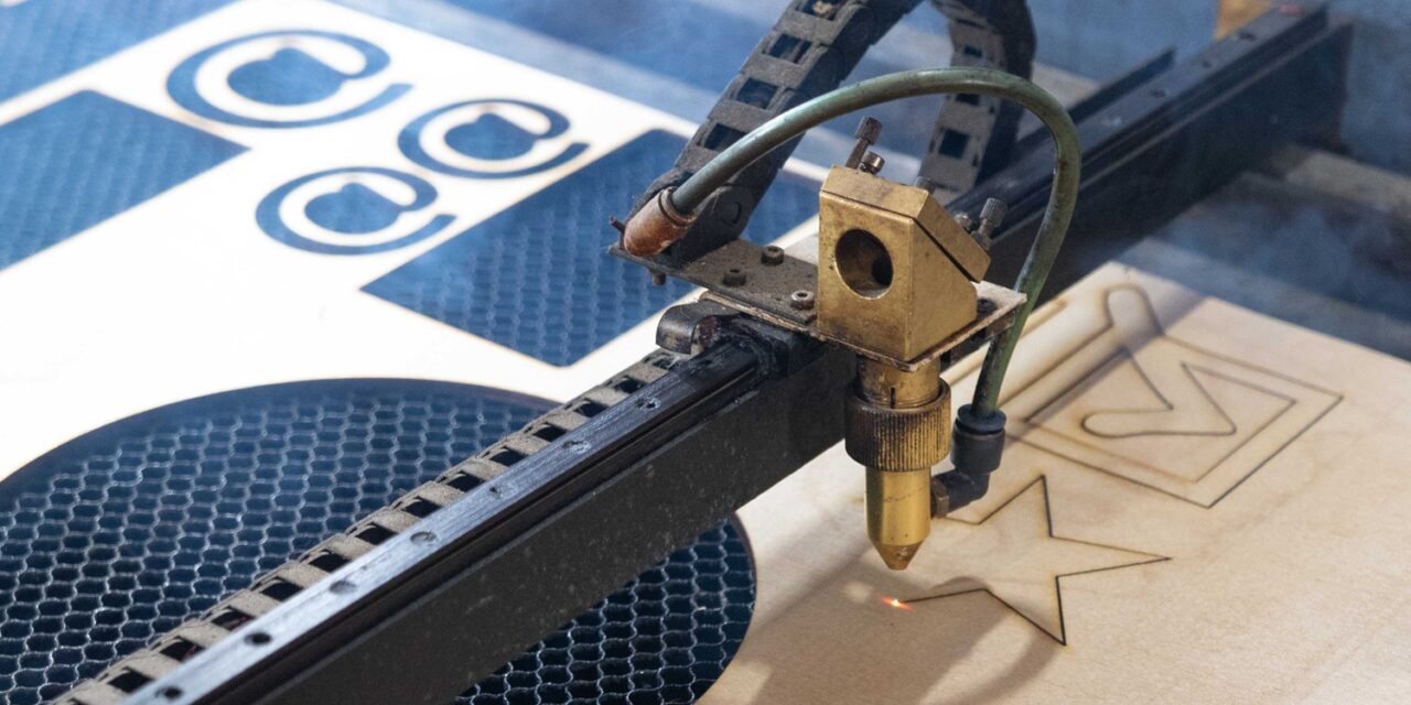
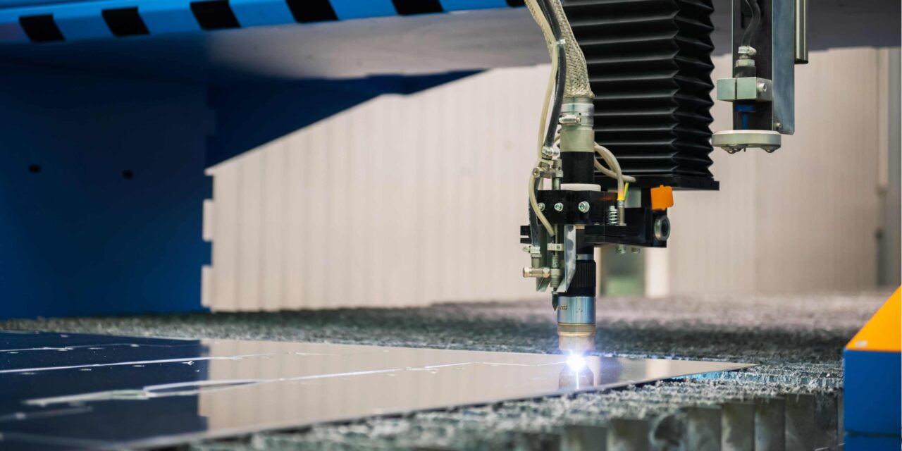
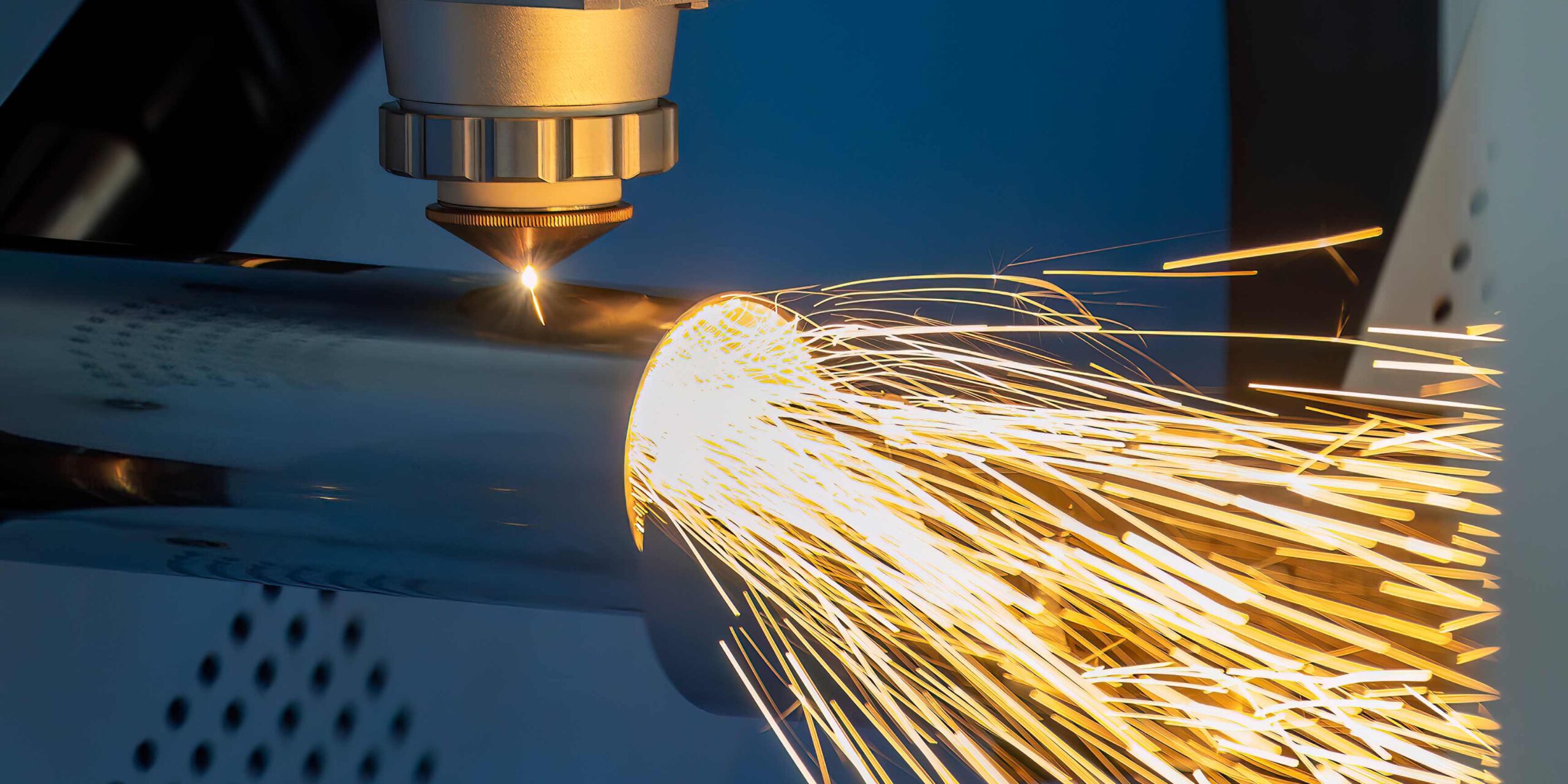
What is Laser Cutting Tolerance?

Laser cutting tolerance indicates the accuracy and the allowable variation in the laser cutter toward cutting the material. In terms of usability, it is the difference between the size of a cut as envisaged and the size actually obtained. Lack of tolerance led to the grounding and corrupting of input signals that, in turn, influences the quality and functionality of the final product. Therefore, a low tolerance level means there are small variations from the required dimensions of the object.

Reasons for Laser Cutting Tolerance

The tolerance limits in laser cutting, in general, depend on several factors. These factors need to be appreciated to advance precision and attain comparability of results.

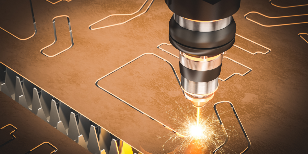
1. Material Type and Thickness

The nature and thickness of the material practically define the laser cutting tolerance. Laser energy is absorbed in different ways by different types of material, which damages the cut’s quality and accuracy. For instance, a larger material thickness may call for high power consumption, and time, resulting in deviations. Some of the basic materials afford high tolerance due to their uniformity, such as aluminum and stainless steel, but those such as wood or plastics can pose some problems.

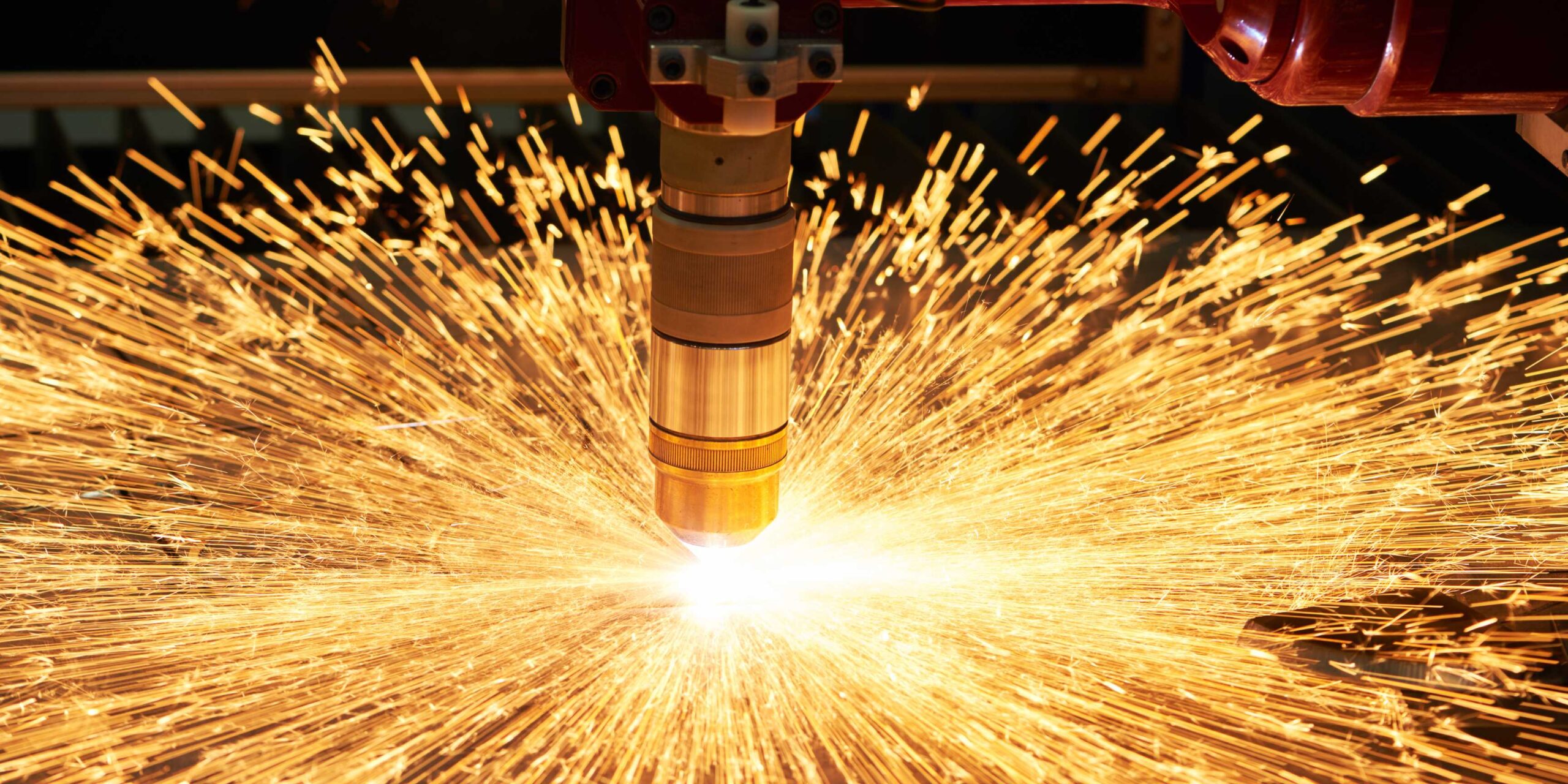
2. Laser Power and Speed

The tolerance levels depend highly on laser power and cutting speed within the manufacturing processes. Heat provides better edges and higher contrasts without a depressing effect on materials Likewise, the cutting speed has to be fine-tuned; if it is set too high, the cuts are not clean; if set too low, there is too much melt under the tool, which influences the tolerance.

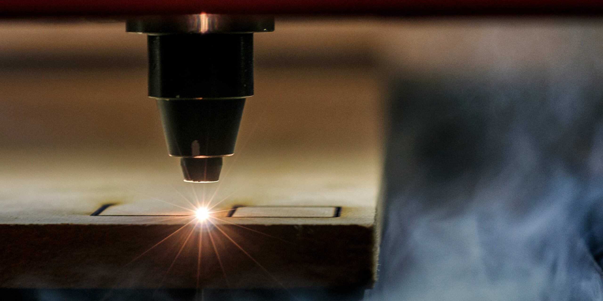
3. Focus and Alignment

Focusing and aligning the laser beam is crucial for high accuracy. Any deviation causes the blade to cut inaccurately and has low tolerance levels. Frequent adjustments of the laser cutting machine ensure that the laser beam is well-focused on the material to be cut.

4. Software and Design

The tolerance is impacted by the software used to design and control the cutting process of the whole program. Still, in Laser Cutting, complex CAD computer-aided design software gives one control over the path of the laser and the dimensions to be achieved on the material. It means any mistake made when working with the design file can easily culminate in an error in the resultant product.

5. Environmental Conditions

Other parameters, such as temperature and humidity, also appear to have some influence on tolerance during laser cutting.

Significance of Laser Cutting Tolerance

Achieving the right tolerance levels in laser cutting is crucial for several reasons:

1. Quality Assurance

High tolerance limits make it possible to obtain the necessary quality products. Tolerance standards in structural elements in sectors such as aerospace or automobiles are paramount to smooth functioning and component’s reliability.

2. Cost Efficiency

Poor tolerance levels may also result in more material being used than necessary, or incorrect parts being made. The concept of tolerance can be used to minimize wasted material, increase the yield ratio and, therefore, increase cost productivity.

3. Product Fit and Functionality

In assembly processes such as those applied in construction, the various components have to fit each other tightly. Fluctuation intolerance results in variation in form and size that affects the assembled product’s final output, integrity and sturdiness.

4. Customer Satisfaction

It is even more important that the obtained and required values should meet certain tolerance levels to satisfy the customer. Brand regulatory trust is created by consistent tolerance levels, which in turn affects manufacturers’ reputations.

Laser Cutting Tolerance Improvement

Laser Cutting Tolerance Improvement

Managing acceptable tolerance levels requires both equipment, technique, and process control.

Here are some strategies to enhance laser cutting precision:

1. Regular Machine Maintenance

Machines should be maintained frequently to ensure the high performance of laser cutting machines. To do this, wipe lenses, align the laser beam, and make sure the mechanical components are in good shape. Equipment which is well maintained is less likely to generate deviations in the size of cuts to be made.

2. Preparation of the Materials

Selecting the material that best fits the job is important. It should be flat and in its best condition to avoid all hindrances during the cutting process. Proper preparation of the materials ensures that the results are consistently obtained.

3. Optimal Parameter Settings

These factors can indicate the right power and focus of the laser and the speed of the laser, which will provide the best results in a procedure. A series of tests should be run on the material and thickness of the size, and the parameter, along with the tolerance, should be set to the required criteria. Automatic systems could also control these parameters to improve consistency.

4. Software

The high-level CAD software will enable the cutter to exercise great control over the cutting process. Look at the design data incorporated into the design files and make sure it is correct.

5. Environmental Control

Stability of the working conditions might also help reduce temperature and humidity fluctuation, which impacts the cutting process. To achieve repeatable performance and maintain tolerance levels, it is advised that investments be made in climate control systems.

6. Skilled Operators and Training

A well-skilled operator enables the organization to achieve its productivity goals and objectives through training.

The tolerance level also depends a great deal on the knowledge that a skilled operator has regarding laser cutting technology. Proper training and frequent updating of systems help them deal with different materials and circumstances.


March 10, 2025
Laser-Cutter-Cut-Metal-1280x640.jpg

Today, laser cutting is widely adopted in the manufacturing, designing, and fabrication industries because of its efficiency and flexibility. Another fruitful question that usually arises is whether it is possible to cut metals with laser cutters. In this comprehensive guide, learn about the capacity of a laser cutter to cut through metal to different types of metals, types of laser cutters and possible limitations facing the process.

Laser Cutting Understanding

The process operates by conning a laser beam on a specific spot, and since the heat is concentrated, it melts, burns or vaporizes the material. To cut material, a stream of gas, which may be nitrogen or oxygen, is used to eject the molten material. Because of efficiency and accuracy, and they are able to cut complex shapes.

Lasers for Metal Cutting.

CO2 Lasers

Carbon dioxide or CO2 lasers are widely used in laser cutting among all types of lasers. The generation of the laser beam is accomplished by these lasers using a gaseous medium, carbon dioxide being the most popular. The CO2 laser is well suited for cutting and engraving non-metal materials such as wood, acrylic and textiles but is not so efficient in cutting metals. This is because the metal absorbs less of a CO2 laser, which makes it a slow process of cutting and processing compared to using a fibre laser.

Fiber Lasers

Fibre lasers are commonly used to cut metals because of their high performance as compared to other laser cutting technologies. These lasers employ a fibre optic cable whose core is subsequently doped with rare earth compounds, namely ytterbium. Fibre lasers have a higher absorption factor in metal and are hence used in the cutting of steel and other ferrite metals. It provides opportunities for higher cutting speed, higher accuracy, and lower operations costs, in contrast to the CO2 lasers.

Nd: YAG Lasers

Another laser-cutting metal option is the Nd:YAG (Neodymium-doped Yttrium Aluminum Garnet) lasers. They are multifunctional and work for cutting and welding, and they are strong for marking. Although they can cut a range of materials, including stainless steel and aluminum, fibre lasers are normally more efficient. However, they are ideal when used to cut non-ferrous materials and other complex shapes and designs.

Metals That can be Laser Cut

Steel

Laser cutting’s most extensively utilized metal is steel, especially carbon steel. Fibre lasers are ideal for this procedure because of the high absorption coefficients. Compared to other cutting techniques, laser cutting of steel offers clean edges and is hence preferred by the automobile, aircraft, and construction industries.

Stainless Steel

Cutting stainless steel with a laser requires more tweaks to the settings and the coolant necessary to prevent oxidation. Stainless steel, however, has some drawbacks inherent to its reflective surface, but fibre lasers can solve these problems due to their high efficiency in the absorption of such material.

Aluminium

Another conductor that is easily cut with the laser cutter is aluminium. It is non-ferrous and has rather good thermal conductivity, and therefore, it rapidly removes heat from the material. All this can make the laser out of focus and end up being less accurate. However, under laser and efficient material cooling conditions, aluminium can be cut with extremely high accuracy.

Copper and Brass

Both copper and brass are difficult materials for laser cutting due to their qualities as heat conductors and reflectors. It could be possible, however, to use a high level of laser cutter and specific parameters. These metals usually work using lesser proficiency lasers or water jet-cutting methods for improved outcomes.

Titanium

It has high strength and low density, which explains why it is used in aerospace machines and medical equipment. Cutting titanium by laser is difficult because of its high melting temperature and tendency for oxidation during cutting. Small laser machines with micro-stepping and laser cooling options allow for getting clean cuts.

Benefits involved in Laser cutting metal

Benefits involved in Laser cutting metal

Laser cutting offers several advantages over traditional metal cutting methods:

– Precision: Laser cutting can produce some very accurate cuts, accuracy or repeatability being usually within .005mm.

– Complexity: The advantage of using a laser cutter is that it can cut out very detailed shapes (and even combine many of them to build complex forms).

– Speed: Laser cutting is also quicker, particularly when using a fibre laser for materials such as metal steel.

– Clean Edges: It creates smooth edges that rarely need a lot of enhancement work to be done.

– Versatility: Laser cutting technologies work effectively on different types of metals.

Some Drawbacks of Using Laser Cutting Metal

While laser cutting metal has numerous benefits, there are limitations to consider:

– Thickness: Laser cutting machines, however, have a limitation on how thick the metal being used is. Thick metal needs more power lasers and time to cut than thin ones.

– Reflectivity: Highly reflective metals, such as copper and aluminum tend to reflect off the surface, which in turn damages the cutting system.

– Oxidation: Some materials, such as stainless steel, are prone to oxidation during laser cutting unless controlled by gas.

– Cost: It has been established that fibre laser-based high-power laser cutting systems are expensive to acquire and use.

Laser cutting has been taken to the next level, giving high levels of accuracy, speed and flexibility in metal cutting. While CO2 lasers are less effective for cutting metals, fibre lasers and Nd: YAG lasers are effective for all steels, stainless steel, aluminum and other difficult materials such as titanium.

For designers, engineers, and even business owners, finding out how laser cutting works and whether these devices can be effectively applied to the metal cutting process will be useful in making certain decisions and ensuring excellent results.


March 5, 2025
Lasers-Cost-Per-Watt-1-1280x640.png

Overview of Laser Systems

Lasers is the acronym for Light Amplification by Stimulated Emission of Radiation, which emits light through the process of optical saturation. Their uses include even cutting and welding of metals in surgeries, optical communications and entertainment. Classifying lasers by their ability to generate a laser beam output in watts (W) counts among the major factors in assessing performance and cost.

Determining Factors of Laser Prices

Type of Laser

The type of laser and its cost per Watt is critical to know how much it can cost.

There are various types of lasers, each suited for specific applications:

– Solid-State Lasers: These use a solid medium like a crystal or a glass. It is mostly cheaper, but it may be even less effective in some cases compared to others.

– Gas Lasers: These lasers are efficient and accurate; they use gas as the gain medium. However, they are more costly than other methods of disposal.

– Semiconductor Lasers: These lasers are frequently used in electronics and telecommunication applications and are less costly in applications requiring low to medium power output but could be relatively expensive at high powers.

– Fiber Lasers: High co-efficiency, and power make fibre lasers widely used in industrial fields. They are cheap to use and do not compromise performance.

Power Output

Laser cost is often proportional to the power that the laser itself generates. In most cases, it is observed that with an increase in wattage, the price of the laser also increases. Because additional components are necessary to develop and maintain high power production.

Application-Specific Requirements

It is also important to consider that the intended application of the laser can play a role in laser costs. Lasers used in industrial applications such as cutting and welding need more power and accuracy, thereby increasing the price. Yet, consumer lasers for home or office use usually have less power and are cheaper.

The cost of lasers is also influenced by the materials used in the manufacturing of the lasers. Superior quality of the optical components, fine mechanical work, and incorporation of new-age electronics boost the costs.

Brand and Technology

It is worth noting that brands with a reputation for delivering quality and durability products will always have their products priced higher. Also, there are lasers that use modern technologies, or when built with higher performance characteristics, they are likely to cost more.

Laser Watt Cost Breakdown

Low-Power Lasers

The cost per Watts is very low in certain low-power usages, like laser pointers and barcode scanners. These lasers are generally within a few dollars to tens of dollars per Watt. These above models are relatively cheaper because they are not as complex as the complicated models, use fewer materials and are more affordable to manufacture.

Medium-Power Lasers

For example, telecommunications, medical devices, and consumer electronics lasers often employ medium-power lasers. These lasers can cost from 10$ to 100$ per watts. The increased cost is connected to the need for higher accuracy, stability, and, sometimes, certain wavelength characteristics.

High-Power Lasers

Industrial applications of lasers, which include laser cutting, welding, and engraving, use high-power lasers, which can be costly. It costs anything from one hundred to several hundred dollars per watts. The main reason is that the required power sources, cooling systems, and most components have to be strong to address the power density.

Ultra-High-Power Lasers

Laser outputs above several kilowatts are employed in a few applications, including the military and research. These lasers can be very expensive; the price per Watt of these lasers is in the thousands. The high levels of power achieved owing to the high complexity and precision and the technology used in their manufacture are reflected in the high prices.

Costs over the last years, their trend and future predictions

Development of Technology

The lasers are gradually cheaper owing to technological improvements. New material, fabrication, and design technologies are rendering lasers more affordable and effective. The development of fibre laser technology has seen costs come down even as the performance improves.

Economies of Scale

An evaluation of the market forces depicts that demand for lasers in different operations has triggered economies of scale. Manufacturers also receive incremental cost benefits from the production of units, therefore making the lasers accessible to the market.

Customisation and flexibility

Lasers can be optimized for certain uses, and this is becoming a trend. It also enables the manufacturers to reduce the cost per Watt, and one can design specific elements and parts to fit particular needs.

The cost can greatly depend upon the type and wattage of the laser, the tasks it’s used for, the cost of production, and the brand. Despite high-power lasers still being costly, progressive technological improvements and elevated production volumes are slowly reducing their cost. Since the demand for laser technology increases each year, more and more people will be able to afford lasers and integrate them into all fields.


December 25, 2024
Laser-Cut-Aluminum-1280x640.jpg

Laser-cutting technology is gradually receiving wide acceptance across different sectors because of the precision, flexibility, and speed offered. Among the metals machining, CO2 lasers slicing aluminum materials are often inquired. In this article, we’ll try to establish how different CO2 lasers perform when cutting this resilient metal and if the laser type is suitable for aluminum in the first place.

A brief on the characteristics and usage of CO2 laser and aluminum

Carbon dioxide lasers are cutting technology that is referred to as CO2 lasers in short form. Its nearly infrared lasers emit light using a CO2 gas mixture of nitrogen, hydrogen and CO2. This light is very intense and is employed in the process of heating or oxidizing a solid (material), for example, metal, wood or plastic.

Aluminum is a versatile metal used in structural drills; it has desirable physical/ mechanical and corrosion characteristics and is extensively utilized in aerospace, automobile and constructional applications. That is, the thermal and electrical conductivity of the metal can influence the laser-cutting process.

Characteristics of Aluminum and Its Adaptability to Laser Cutting

Because of the properties of aluminum, this material is somewhat difficult to apply with laser technology to cutting. It gives high reflectivity that a major part of the laser beam can be reflected off the surface without being absorbed. By reducing efficiency and more usage of energy, the cutting tools will wear out sooner and take more time to cut.

Secondly, aluminum creates a cover layer of oxidation on its surface and thus can act as a shield against rusting but also presents a challenge to the laser cutting process. This oxide layer needs to be passed through to allow the laser to cut through the metal and get an effective result.

How CO2 Lasers Work

CO2 lasers operate by passing current through gases inside a laser chamber. The excited gas releases its energy in the form of a laser beam, and this can be aimed and converged to bring about the required cutting topology. The energy from the beam is transferred to the stuff, in this case, heating the material and vibrating it enough to melt, evaporate or burn to make the cut desired.

Laser Cutting Aluminum: Advantages and Disadvantages

Using laser cutting in aluminum offers a number of advantages over conventional cutting techniques due to enhanced accuracy, a slim margin of heat-influenced area, and enhanced rates of cutting. These advantages may lead to the generation of improved quality parts and decreased manufacturing expenses. One limitation of laser cutting is that if aluminum, then it has limitations in reflective material as well as the coating chances with oxide layers.

Technical Issues Involving the Utilization of CO2 Laser for Cutting Aluminum

Cutting Aluminum

For a CO2 laser working the right technological parameters have to be there to enable proper cutting of the material.

These factors include:

– Laser power: It is possible to increase the density of the laser in order to avoid the influence of the aluminum’s high reflectivity and the presence of a thin oxide layer on its surface. This helps put the laser through the material in question, hence providing a cleaner cut through the item.

– Cutting speed: Using a low cutting speed will enable the laser beam to take sufficient time to permeate the material besides breaking through the oxide layer. It could cause a cleaner and a smoother incision.

– Assisting gases: Thus, to optimize the cutting process, an assisting gas can be applied to facilitate the removal of molten metal from the cutting area. The typical helping gases of laser-cutting aluminum are oxygen, nitrogen and air.

– Focus: During cutting aluminum it is very important to set the laser beam correctly. When the beam is well-focused, then expect a neat and accurate cut.

A comparison of CO2 Lasers with other laser types

But there are other types of lasers used in cutting aluminum, such as fibre laser and UV laser. In that case, these lasers may have advantages over CO2 lasers with respect to speed of cutting and utilization. But CO2 lasers also still count as popular because costs are relatively lower than most and can cut through most material types.

The typical uses of CO2 laser cutting of aluminum

CO2 laser cutting of aluminum is used in a wide range of industries and applications, including:

– Aerospace: Laser cutting is applied in the fabrication of accurate components of aircraft and spaceships.

– Automotive: Cars employ aluminum in the body and other parts, and cutting normally involves the use of CO2 lasers.

– HVAC: Today most of duct work, vents and other HVAC products are fabricated from aluminum using the laser cutting technique.

– Medical: Medical devices and equipment made of aluminum components are cut with the use of CO2 lasers.

– Architectural: Other applications of laser cutting include making clips and panels, metal cladding, and certain architectural embellishments.


December 15, 2024
Weld-Aluminum-1-1280x640.jpg

Aluminum is one of the materials to which laser welding is applied, and taking into account that it can be utilized for joining different materials. Several properties of aluminum alloy are desirable, such as light weight, high strength-to-weight ratio, and good thermal and electrical conductivity. Over the years, there has been a developing interest in laser welding of aluminum because of these benefits: precision, high energy density, and minimal heat input to other parts of the material.

This article will describe the possibility of welding aluminum using this technique, the different types of lasers useful for welding aluminum, the benefits and constraints of laser welding aluminum, and some uses of laser welding aluminum in various industries.

Types of Lasers Used for Aluminum Welding

Laser Welding of aluminium alloys is a crucial process in the manufacturing of automotive vehicles, wireless communication equipment and countless applications involving lightweight and high strength structure materials.

Various classifications of lasers used for al-welding are possible, and they are all characterized by their advantages and disadvantages.

Some of the most commonly used lasers for this purpose include:

1. Fiber Lasers: This type of laser has recently found its way into aluminium welding applications as a result of its high efficiency and low costs of operation. The source has a high beam quality and can deliver high power in a localized area, which is important for welding thin aluminium foils. Also, as pointed out earlier, fibre lasers have high duty cycles, and the beam quality is very good for long distances; hence it is suitable for automation.

2. CO2 Lasers: CO2 lasers have long been used in welding aluminium. They have low cost and can produce high power levels, which can be useful when welding thicker aluminium sections. But, as output beam quality, they are not as good as fibre lasers, are more susceptible to degradation, need more maintenance, and have a lower duty cycle.

3. Solid-State Lasers: These lasers have lower power than fibre lasers but have greater beam quality. They are intended for welding thin aluminium sheets and where increased accuracy is needed.

Pros of Laser Welding Aluminum

Laser welding reveals the following advantages over other types of welding regarding aluminium.

Some of these advantages include:

1. High Precision: Automatic welding is less sensitive to weld pool movements and produces narrow welds with low distortion levels. This is especially important where thin aluminium foils are used because any heat introduced to the foils will lead to warping or the formation of other undesirable features.

2. Minimal Heat Input: Traditional welding procedures differ from laser welding since the latter has a small heat influence on the surrounding material. This minimizes thermal injury and makes it possible to join delicate components without causing heat-related failure.

3. High Speed: High speed of laser welding, reduces the labour cost. Furthermore, the laser beam contains high energy density, which ensures deep penetration welding suitable for welding thick aluminum sections.

4. Automation: Laser welding can be easily incorporated into an automated system; this could help increase productivity, reducing errors ands.

Laser welding Aluminum: Key Issues

Laser welding Aluminum

However, as earlier mentioned, there are some drawbacks of laser welding aluminum, although the fact that this process has many benefits justifies its use.

Some of these challenges include:

1. Reflectivity: Aluminium has the issue of laser reflectivity since the material itself has reflective properties. This can cause a loss of energy, weld penetration, and efficiency decrease, as well as weld defects, such as keyholing or lack of fusion. The problem is solved in some laser welding systems by employing pulsed welding, which encompasses the modulation of the laser power density to enhance energy penetration.

2. Surface Oxides: Aluminum is easily oxidized to form a coherent oxide layer on the surface, which is nearly impossible to remove using the laser beam. To improve this latency, the aluminum surface must be prepared so that the surface is free of contaminants, which will interfere with the welding process and shield the weld area from surrounding atmosphere during welding.

3. Residual Stress: Cracking or warping can be caused by residual stress left in the welded material by laser welding. To reduce this problem, the welding process is to be tightly regulated; and in some instances, the post-welding heat treatment is likely going to be necessary.

Laser Welding and its Uses in Aluminum Industry and its Detail applications

Laser welding in aluminum involves the following: Some common applications include:

1. Aerospace Industry: Laser welding is used to join different parts including fuselage sections, wing panels and landing gear since aerospace most of its components from aluminum. Laser’s welding provides the accuracy and the required strength for such applications and at the same time reducing the weight of the component.

2. Automotive Industry: It is used widely in auto mobile industry currently since it is light in weight but stronger than steel. Most automotive companies today employ laser welding to connect aluminum parts including the skin, space frames, chassis and suspension systems, the benefits being it is very rigid, light and does not rust.

3. Solar Panel Manufacturing: Because aluminium is superb at transmitting heat and electricity, it is favoured in the production of solar panels. Laser welding is employed for the joining of the aluminum frame to the solar cells which produce a robust and assiduous yet lightweight construction that can endure the vagaries of outdoor settings.

4. Medical Devices: Owing to its biochemical compatibility and its ability to resist corrosion aluminum is commonly used in development of medical devices. Laser welding is employed to weld aluminum parts in the medical products including surgical tools, implants, and dentures to have a severe, flawless, and germ-free bond.


December 5, 2024
1-1-1280x640.jpg

Using fabrics in different projects that can be attached to metal surfaces brings a lot of potentialities in the function of upholstery, fashion designing, and home interior decoration, among others, such as mixed media art. The procedure can also be a bit delicate since glass and carbon fibres do not share many characteristics, such as flexibility, mass or electrical conductivity. Here, you will find an overview of different techniques that are used in attaching fabric to metal, the advantages and disadvantages of each, and step-by-step instructions on how to sew them.

Materials Needed

To effectively attach fabric to metal, you’ll need the following materials:

1. Any fabric, which could be natural fabric, synthetic fabric or blended fabric.
2. Sheet metal or metallic piece (copper, brass, iron steel or any other preferably a conducting material).
3. Adhesive or fasteners
4. Sandpaper with medium abrasive grit (220 and higher).
5. Ruler
6. Pencil or fabric marker
7. Cutting tools either scissors or a utilitarian knife.
8. Cutting mat
9. Work gloves (for safety)
10. Clamps (if needed)

Preparing the Metal Surface

However, some preparations should still be made before attaching the fabric to the metal. This includes stripping by brushing off any burr, rust, paint or any material that will hinder the fabric from sticking to the metal.

Cleaning the Metal

First of all, moist the surface with water to ensure that the metal is free from dust and other dirt particles. If that is present, you can scrub it off with a wire brush or steel wool.

Sanding the Metal

To enhance that critical connection, you will be forced to slightly roughen the surface of the metal. It is then recommended that to use sandpaper of 220 grit or higher to sand the metal – covering the whole area of the substrate where you intend to join the fabric too. It can be done using a handheld sanding block, or sanding disk of an electric sander, or just sandpaper pasted to a wooden block. Make sure you have safety glasses and work gloves to protect you from objects that may fly around during handling.

Fabrics are cut according to the size required

Fabrics are cut according to the size required

When the metal surface is ready, the fabric needs to be measured and cut to fit the metal’s surface. For a proper fitting, you can stencil the measurement of the metal onto the fabric of use, cutting a piece of fabric slightly bigger than the metal dimensions.

Marking the Fabric

Measure the area on the fabric that you want to attach to the metal with a ruler and pencil or fabric marker. You should then opt to add the seam allowance around the edges to provide tight margins.

Cutting the Fabric

If your fabric has been drawn with lines, cut them using a pair of scissors or a utility knife.

Attaching Fabric to Metal

We’ll explore three popular methods: adhesive, staple and rivets.

Adhesive Method

Copper and brass worked well when the method was employed with thin blankets of fabrics such as perlite cotton and other lightweight synthetic textiles.

Choosing the Right Adhesive

Choose an adhesive for connecting two dissimilar materials such that one is metal and the other is fabric. Using E6000 craft adhesive or if it has to be a fabric as well as leather adhesive with a little more thickness might be ideal.

Applying the Adhesive

Spread a thin, even layer of sticky glue over the sandwich part of the metals that were sanded and to where the fabric must be fitted. For these adhesives, one can use a brush, or an applicator gun also depending on the adhesive in the process.

Attaching the Fabric

Put the fabric over the metal and arrange the edges as necessary. That is, fold it tightly on the surface of the metal with force from the middle to the edge. Eliminate any air bubbles by running a flat implementation tool, such as a butter knife or any straight edge over the polymer layer.

Staple Method

Suitable for rigid and soft metal and heavy fabrics such as denim or canvas material, this works perfectly.

Choosing the Right Stapler

Choose a stapler that will handle the thicker range denoted by the point range and that is made for such use. An upholstery stapler or a fabric stapler will apply the most effectively for this.

Attaching the Fabric

Start by laying the fabric right on top of the metal, and then ensure you have the edges correctly aligned. Pull the fabric tight with one hand and, using the other, drop a staple through the fabric and the metal in order to fix it. Carry on working on the edges, staple occasionally, approximately one inch at a time, or wherever necessary to keep the fabric on the board.

Rivet Method

Rivets provide a strong permanent fastener similar to metal and heavyweight fabrics. This method can be used for cosmetic or utilitarian reasons, such as that of a patch or piece of apparel no longer functional.

Choosing the Right Rivets

When selecting the rivets, one should ensure that they are slightly smaller than the thickness of the fabric. Copper, brass or steel rivets are chosen for use commonly;

Preparing the Rivets

For the final step, crimp or pin the rivet, depending on the type and size of the rivet. You will get only the cup and a seam of the tail at the bottom, which will be situated beneath the material.

Attaching the Fabric

Position the fabric over the central part of the rivet cup and make sure that the fabric is parallel to the metal surface. It is then flattened over the metal surface using the rivet setter or the hammer to make a crimp head of the rivet. Carry on this process right along the edges until the fabric is joined to the backboard well.

Finishing Touches

After that, an additional ornament such as fringe, lace or beads will give a finished look to this particular piece of metal.


November 15, 2024
1-2-1-1280x640.jpg

Laser cutting is gaining acceptance in many fields as a way of cutting metals, plastics, and other composite materials. The advantages obtained by applying the laser in cutting include increased accuracy of the cuts, short time for preparation, minimal loss of material, and the potential to create intricate cuts in curved patterns. Of all the materials, one material that can be laser cut is aluminum. However, can a diode laser cut aluminum successfully?

As most metal cutting applications involve aluminum, this article will focus on understanding the capacity of diode lasers to provide cuts to aluminum and the effects and constraints of this capacity.

Diode Lasers: An Overview

Small semiconductor devices that radiate intense monochromatic and highly collimated light beams, diode learners, or laser diodes. Because of their relatively small size, low cost, and excellent efficiency, they are employed in numerous applications. The PN junction is a diode laser principle in which light generation is achieved by passing an electric current through which electrical and optical fields are combined.

Diode lasers can be classified into two main types: Fabry–Perot and Distributed Feedback (DFB) lasers. The most familiar type of Fabry-Perot laser employs multiple reflections and produces a wide-spectrum light beam. DFB lasers, on the other hand, are much more complex than Fabry–Perot lasers and have distributed grating, hence exhibiting light emission in a single mode and narrow spectrum, respectively.

Diode lasers can emit light at different wavelengths depending on the end user’s requirements. The most frequently used wavelength is 808nm, which is suitable for cutting and welding carbon steel and stainless steel. However, other wavelengths are also available in appropriate uses, namely 940 nm, 1064 nm, and 1320 nm.

Slicing of Aluminum through Diode Laser

Diode Laser

The low density, rust-proof characteristics, and high thermal and electrical conductivity of aluminum make it an ideal material that could be widely used in various sectors today. Nevertheless, this metal is rigid to work with because of its high melting point and ability to reflect heat and/or light; to elaborate, mechanical cutting and plasma cutting are challenging to perform on aluminum.

Today, laser cutting is widely used to cut aluminum as a better option to other methods. The operation of the laser on the aluminum surface lets the power density be high enough to melt or evaporate the material necessary to make a definite and clean cut. The parameters pertaining to laser cutting are laser wavelength, laser power, laser spot size, laser speed, and the nature and thickness of the aluminum.

Diode lasers are not popular for the cutting of aluminum and this is because; though the diode lasers can be used for cutting of aluminum, it can only be done if the correct parameters have been applied. For clean and smooth cutting of aluminum material, a diode laser should have high power-rated output, most preferably above 1kW, and concomitant laser wavelength of the diode laser should be easily absorbed by the metal material. Other laser parameters should also be adjusted to the spot size to equal the cutting speed and edge quality.

Application of Diode Lasers to Cut Aluminum: Strengths and Weaknesses

Diode laser which is cheaper is more suitable for small and medium enterprises than CO2 or fiber lasers. Furthermore, diode lasers are characterized as having a long useful life and low level of maintenance, which makes them cost-effective devices.

However, some drawbacks can be observed when using diode lasers for cutting aluminum. Cutting process is likely to occur at higher rates of power and at slower rates at times compared to other lasers. Consequently, production time and power utilization may be increased.

Further, it is discovered that diode lasers are likely to give a marginally inferior cut quality when used on aluminum, particularly on thick material or complex shapes. Another disadvantage of diode lasers may be a higher size of the heat affected zone compared to conventional lasers which can extend its adverse effects on the material surrounding the cut.

Although diode lasers can cut aluminum, one should not use them in the situations where accuracy is paramount, or where the aluminum is particularly thick. Other similar types of laser that can work better are CO2 or fiber laser in relation to the rate of cutting, sharpness of the edge and minimized heat affected zone.

Characteristics of the cutting process and factors influencing it

Several factors can influence the quality and efficiency of diode laser cutting in aluminum, including:

1. Laser wavelength and absorption: The optical absorption coefficient of laser light by aluminum is not very high, especially in the near-infrared range of wavelengths (800 – 1064 nm) standard to diode lasers. Higher power losses and lower cutting rates can follow. To enhance the absorption some changes in the laser parameters or a surface coating may be applied as a part of the preprocessing stage.

2. Laser power and focus: The material cutting rate and edge quality all directly depend of the chosen laser power and focus. By use of higher power levels and finer spot sizes, the cutting speeds are always higher, and the edge quality is well enhanced. Nonetheless, the most suitable laser parameters with regard to thickness and quality of aluminum could be different.

3. Cutting speed: There is a strong correlation between the cutting speed and quality of cut and the heat affected zone. Increasing cutting speeds makes the cuts smoother, and also reduces the amount of heat that causes degrading of the edge, but it reduces the cutting performance in equal proportion. Proper control of the cutting speed suited to a particular job is absolutely critical in order to provide the highest possible value of the ratio between the speed and accuracy.

4. Assist gas: The cutting operation is made better by removing molten metallic and chips from the area being cut by using an assist gas like nitrogen or oxygen. Cutting speed and edge finish will vary, depending on the type of assist gas metered and the pressure used.


November 10, 2024
Laser-to-Cut-Aluminum-1-1280x640.jpg

Laser cutting is one of the production processes that is widely used in industries for cutting matrices such as aluminum. They are somewhat difficult to laser cut because aluminum is both highly reflective and has a comparatively high melting point. In this article, we are going to unveil the various considerations before arriving at the best wattage for laser cutting of aluminum and also, the wattage to choose for the various results.

Learning More About the Difficulties Involved in Cutting Aluminum

It is a soluble material well suited to be used in numerous industries like Aerospace, Automotive, Construction, etc. When laser cutting aluminum several problems that must be taken into consideration when deciding on the correct power of the laser.

Reflective Surface

Aluminum in particular is highly reflective, thus when the laser strikes the surface, a great part of it is reflected back and little of the energy is actually absorbed by the material. On the other hand, this makes it less easy for the laser to melt and vaporize the aluminum, or (in general) the technology of cutting is poor or requires more laser power.

High Melting Point

One issue with working with the material aluminum for example is that it has a higher melting point than plastics so it cannot be cut with a typical laser. Second of all, aluminum, in general, is characterized by higher thermal conductivity, and therefore heat is immediately transferred far from the cutting zone, which makes the cutting even more difficult.

Criteria that Determine the Laser Power

Before the procedure aluminium ought to be evaluated and therefore the precise wattage of a laser ought to be chosen reckoning on the thickness of aluminium, speed, and quality of the cut.

Material Thickness

Thicker aluminum materials mind demands more laser power to offer a clean edge with no burr formed on the material’s surface. In general, as with thickness generally, more energy is needed to melt the material and vaporize it.

Cutting Speed

The desired cutting speed in the project to be done will also determine how much wattage the laser used will have. If greater cutting rate is needed, it might be essential to use a stronger laser in order to preserve cut quality.

Cut Quality

Edge finish and cut tolerance will also have a bearing on the power output of the laser; other characteristics. More power causes a better shave, and thus a cleaner cut than low power may cause a rough edge or even more dross.

Suggested Laser Wattage for Cutting Aluminium

Cutting Aluminium

These factors may be used in forming guidelines for general laser wattages used to cut aluminum.

Thin Aluminum

In case of thin aluminum materials which are less than 1mm thickness, a fiber laser with power of between 500 – 1000 watts is adequate in delivering a good cut. These lasers are precise and fast, therefore ideal for thin aluminum sections.

Medium-Thick Aluminum

For materials of mid thickness in aluminium, that is, thicknesses ranging between 1mm and 3mm, a fiber laser with power of between 1000W and 2000W is most suitable. This extra power of laser necessary to melt material rapidly, to remove the thin layer of the material and achieve the high quality of edge.

Thick Aluminum

For thick aluminum materials their thickness should be more than 3mm in which case high power laser cutter is required to make clean cuts and this could be with power from 2000w-3000w and above. These lasers can produce the amount of energy and the narrow focus necessary to sever through thick material in a good manner.

Additional Considerations

Apart from the laser power there are other parameter that can affect aluminum while cutting including the assist gas, focal length, and laser beam quality.

Assist Gas

As you continue cutting, the debris and dross from the previously cut area can dilute with the kerf, which can result in poor edge quality and material discoloration, hence by using an assist gas, such as nitrogen or oxygen, you get to increase the cutting efficiency, as well as help to vacuum the debris and dross from the cutting area.

Focal Length

The focal distance of the laser cutting head was optimized by varying and determining the appropriate focal distance for the different aluminum materials and their thickness. For a sharper beam and better cutting operation, a shorter focal length will be required for thicker materials.

Beam Quality

The quality of the laser beam used is essential while cutting aluminum since the use of a low quality beam reduces the efficiency of the cut made. In cutting aluminium, the quality of the laser beam used in the system has to be the best so that the proper cut is achieved.


November 5, 2024
How-to-calculate-the-shear-force-and-bending-moment-1280x640.jpg

One of the most critical areas of investigation in structural engineering is the behavior of beams under load. These behavior characterizations are commonly defined by the shear force and the bending moment. Shear force and bending moment diagrams are beneficial and popular aids that engineers use to explain, design, and anticipate the behaviour of beams under different loads. In this article, let us discuss the procedures for determining the shear force and bending moment together with the methods for producing the respective diagrams.

Shear Force Calculation

Shear force (V) is the force acting on a beam segment’s point perpendicular to that segment’s longitudinal plane. They occur from the unsymmetrical sharing of external load and reactions that act on a specific part of the structure. When determining shear force, it is possible to use three approaches: the direct, Graphical, and Numerical. In this case, we only discuss the direct method, which is much simpler and relevant for most applications.

Definition of Sign Convention

When determining the shear force, there must be a convention of its sign, which must be positive or negative.

The most common convention is as follows:

-It should also be mentioned that a positive sign is assigned to any vertical forces acting downwards.

-It should be noted that the vertical forces are hostile specifically.

-Left shear forces are positive, and right shear forces are hostile.

Step-by-step Calculation

1. Determine all point loads, distributed loads, and reactions located at the beam.

2. Generally, we select an origin (slightly to the left of the beam) and assign the intrinsic + ve and – ve signs to the former.

3. Subdivide the beam into a small elemental length (Δx, which is a differential length).

4. Find out the resultant force applied on each part of it (with point loads as well as the distributed loads and the reactions).

5. Force that stays at a specific point of the beam is the sum of shear forces accumulated in the narrowed segment of the beam located on the left side of this point only.

Example: A simply supported beam having a point load (P) at mid-span and a uniformly distributed load (w) covering the whole span of the beam of length (L).

1. Point loads: P (at the center of the beam)

2. Distributed load: w (which is evenly distributed throughout the span of the beam).

3. Reactions: R1 and R2 (at the supports)

4. Calculate the reactions: R1 = R2 = wL/2

5. Break down the beam. The shear force at any point to the left of the center is given by the expression:

for ( x < L / 2 ) ;
x : V ( x ) = w ( 0 ) – w ( L ) x + w L / 2.
V(x) = w(x) – P + wL/2 for L/2 < x ≤ L

Bending Moment Calculation

Force, what was felt at a beam segment, due to load transfer along the length of the beam is called bending moment (M). It is the outcome of an external loads reaction and shear forces which come into play in any fixed segment of structure. It is also possible to calculate the bending moment through a direct method, which deserves our attention below.

Definition of Sign Convention

Similar to shear force, a sign convention is necessary for the calculation of the bending moment:

-Clockwise moments are good ones.

-Moments that are counterclockwise are negative.

-Moments of the applied loads occurring at the left of the point are taken as positive, and at the right of the end, are taken as unfavorable.

Step-by-step Calculation

1. All the point loads, distributed loads, and reactions that are on a beam should be determined.

2. Pick a reference axis (typically the left end of the beam), and then assign plus (+) and minus (-) signs.

3. Subdivide the beam into small segments of equal dimensions required to be considered (Δx).

4. Point load, distributed load, reaction, or shear force stretches are determined, then, the force or net moment through segments of a beam for point loads, distributed loads, reactions, or shear forces.

5. The algebraic sum of moments of the forces applied to the beam up to a given point that is acting on the beam segment.

Using the same example as before, the bending moment at any point x to the left of the center is given by the expression:

M(x) = w(x^2)/2 – wLx/2 For 0 ≤ x ≤ L/2

Shear force and Bending moment diagrams

These are to be sized after getting the shear force and/or bending moment values of a segment, and the respective diagrams may be plotted. They show how shear force and bending moment change across the beam (and give a graphical description of how a beam behaves under load).

The steps for plotting these diagrams are as follows:

Shear Force Diagram

1. Shear force values are graphed and mapped to the respective points on the beam.

2. Connect the points together in perfectly lit, straight, and beautiful elegant lines.

3. If necessary, find the slope of the distributed loads that will be useful in extending the lines between the data points.

Bending Moment Diagram

1. Plotting the variation of bending moment as a function of a specific coordination point on the beam.

2. Make a straight line between the points.

3. If necessary, use the slope of the distributed loads and the shear force diagram in order to guide you in drawing lines between the data points.

4. Find points of inflection which marks the change of direction of bending moment from tension to compression or vice versa.

Through these diagrams, engineers are well positioned in identifying areas that need more reinforcements within beams. They can also calculate deflection of the beam, stress to be experienced by the beam, structural capability of the beam and load to be borne by it to ensure it can safely exert under the given loading conditions.

Thus, simple shear force and bending moment calculation and creation of the corresponding diagrams are considered a crucial set of competencies for structural engineers. The engineers can follow numerous steps accordingly and calculate different conditions of beams under load and guarantee that the corresponding structures will be safe and efficient.


October 25, 2024
How-to-Cover-a-Metal-Bed-Frame-with-Fabric-1280x720.jpg

If you have a simple metal bed frame, then you can make a significant change in the style of your bedroom by covering it with fabric. It makes the room look less clinical and lets you make the bed conform to your interior design scheme. In general, combing a metal frame does not require profound sewing skills or a significant number of sewing supplies. Below are the essential measures to follow when installing fabric on your bed frame.

Things You’ll Need

– Metal bed frame
– Any fabric you choose (the total fabric should be 1- 1.5 times the total area to give wool enough material to wrap around corners and staple.)
– Staple gun and staples
– Scissors
– Tape measure
– Pencil
– Foam padding (optional)

Preparing the Bed Frame

Preparing the Bed Frame

Also, before making a cover, clean the bed frame, ensuring there are no sharp edges or projecting parts that could lead to the fabric’s tearing. This way, you sand down any rough surfaces using some sandpaper. For this first step, gently clean the frame using a vacuum cleaner to get rid of the dust and other particles.

We have provided instructions on how to attach foam padding sheets to the frame – either use industrial-strength Velcro or glue if needed. The padding serves as an additional measure of comfort and provides a more usable contact surface when leaning against the frame. As an added advantage, it also makes a smooth surface that will allow the craft to be coated with fabric quite easily.

Measure Carefully 

Measure on each component of the frame – the head part, the bottom part, the two side parts, and the horizontal top parts. This is because one needs to add several inches to each measurement to be able to pull taut across the surface. Be sure to add several more inches for wrapping of the corners and for stapling the fabric underneath a frame. Accuracy should be measured twice in order to get correct values.

Cutting the Fabric Panels

Cutting the Fabric Panels

From your chosen fabric, draw and cut panels that are slightly larger than the specific dimensions you got by 1- 1.5 inches on all sides. Out of a plywood cut, rectangular pieces of a proportional size were cut for the headboard, footboard, and side rails, respectively. The top rails and the legs should be cut to square or rectangular. Arrange the material with distinctive patterns to the best parts of the house.  But make the panels labelled so they are easier to sort.

Staple on Fabric

Work one section of the frame at a time, starting in the middle and draping a fabric panel tight, but not overly so, onto the surface. You can simply fold in the corners and then use painter’s tape to keep everything in position while painting. Then staple one corner and keep going along the channel to staple every 1-2 inches of the side. Tug the fabric towards and make some adjustments on the areas with folds or waves.

For corners, we should remove the triangular-shaped pieces from the spare fabrics. Fold the three triangles at the bottom neatly, then staple the triangles at the back of the frame to camouflage staples.

Finishing Touches

Feel the upholstered frame with your hands from raised or spongy corners or other aberrant places. Rest the fabric tight and sew more staples if necessary to make the fabric tight. Finally, cut off any that is overhanging the edges with scissors if you want a neat appearance.

Caring for the Fabric

The covered bed frame should be dusted often, preferably on a weekly basis, using a soft brush attachment so that dirt and grime that can be abrasive to fabric won’t accumulate on the object. It is advisable to treat any spillage with an appropriate cleaner to avoid these getting deeper into the fibers. Down the line, some stretch of the fabric could become lax due to movement of the metal frame; try to re-stretch and re-staple the fabric every couple of years.

Tips and Considerations

– Install some soft sponge on the interior side to enhance their comfort, besides covering most parts of the exterior with fabric.
– Make sure that there are no staple or sharp points protruding to the fabric side – flatten those that are sticking out.
– For its durability, treat specific areas as necessary; use a light vacuum brush on a daily basis.

Conclusion

Adjusting a metal bed frame means adjusting the bed, and consequently, the entire room, to be softer and cozier. The time spent in having accurately measured and cutting the fabric besides stapling and making it smooth produces upholstered furniture looking furniture. Switch up the textile of furniture seasonally or when doing a change of furniture for the quickest room revamp. It may not take much more than two or three hours on your part to have the bed frame wholly standardized and fabric covered in accordance with your desired style.


CONTACT DETAILS

Our Company


(905) 643-7710

905 643-7720

info@gfmachineshop.com
WORKING HOURS

HOURS OF OPERATION


Mon – Fri : 8:00 AM – 4:30 PM

Emergency: after hours service is available
GET IN TOUCH

Follow Our Activity